Pipelines are built for transportation to consumers of natural gas. Design their design organizations that have received a license to carry out such work. For the installation of gas pipelines, pipes of various steel grades are used in various ways (at different temperatures and pressures). According to the production method steel pipes for gas can be divided into seamless (hot-formed and cold-worked) and welded (with a straight and spiral seam).
Steel for the production of products of this type must comply with GOST 380 88. Specifications regulated by GOST 1050 88. The thickness of the pipes is determined using calculations, given that for an underground pipeline it should be at least 3 mm, for overland pipelines - at least 2 mm. The gas pipe must have a certificate. The documents must indicate the manufacturer, GOST, steel grade, production method, test information, batch number, quality control mark of conformity.
Scopes of steel pipes for gas pipelines:
- - in gas supply systems with pressure up to 1.6 MPa - water and gas pipes (GOST 3262-75) with nominal bore up to 80 mm;
- - in gas pipelines with different pressures - seamless steel pipes (GOST 8734-75 and GOST 8732-78) that withstand pressure up to 10 MPa;
- - in gas pipelines with high pressure - longitudinal welded pipes (GOST 10704-76) with a diameter of 30 to 426 mm and a wall thickness of 3 to 12 mm.
The advantages of steel pipes for gas
Steel pipes for gas pipelines:
- - durable;
- - resistant to internal pressure;
- - linear expansion of steel pipes is 20 times less than that of pipes made of polyethylene;
- - one hundred percent gas tightness, which eliminates gas leakage.
The disadvantages of steel pipes for gas:
- - tendency to corrosion, leading to a decrease in the internal cavity;
- - relatively large weight;
- - laborious and time-consuming installation;
- - high thermal conductivity, leading to the formation of condensate on the outer surface, as a result of which the corrosion process begins;
- - welded joint - the most vulnerable to rust;
- - restrictions on the length of the delivered products;
- - limited flexibility.
Gas pipeline installation
Gas requirements:
- - the situation should be fully consistent with the project;
- - on the gas pipeline the insulation with which steel gas pipes;
- - all connections must be completely tight, not leak-proof;
- - pipes must fit snugly to the base;
- - the bed should be kept;
- - Mandatory elements are water drains (for condensate drainage from the outer surface) and expansion joints (to neutralize the linear expansion of the pipe).
The trench for the gas pipeline cannot be prepared in advance. Its bottom should be cleaned of debris and stones. The gas pipeline is mounted from separate elements that are welded outside the trench. When lowering individual elements into the trench, impacts against the walls or the bottom are not allowed. If the gas pipeline is laid in the winter, the trench should be dug to not frozen ground immediately before laying the elements. On rocky soils, sand bedding (approximately 200 mm) is required.

Insulation of the outer surface of steel pipes
If the pipeline is laid in the ground, it is exposed to corrosion and stray currents that destroy its walls. To extend the service life of pipes, they are coated with various anti-corrosion insulation materials at the factory. During transportation and installation, pipes should be handled carefully, since it is quite difficult to restore insulation in the field.

During installation, nevertheless, work is required to insulate the joints that are formed after welding of individual elements of the pipeline. For this purpose, various anticorrosion coatings made on the basis of bitumen and roll materials (kraft - paper or polymer) are used. Depending on the properties of the soil, anti-corrosion insulation can be normal, reinforced or very reinforced.
The pipe is cleaned to a metallic luster. Then a primer is applied to it. Bituminous mastic is prepared in bituminous boilers and applied to the primer using a watering can while it is hot. Over the mastic, a roll of insulating material is wound over the lap.
Internal insulation of steel pipes
Epoxy materials are most often used for internal insulation of steel pipes. They prevent corrosion of the inner surface and the occurrence of other deposits, keeping the throughput constant.
The pipeline for transporting gas consists not only of steel pipes, but also of valves, hydraulic valves, expansion joints and condensate traps. Cranes are made of cast iron, steel and bronze with a diameter of 15 - 700 mm. The gates act as shut-off devices - to shut off the gas, water is supplied to the pipeline, which fills the lower part of the shutter, interrupting the flow of gas. To reconnect the gas, water is removed by purging. Strength tests of the valves are carried out at the factory.
Compensators are mounted in wells and connected to the gas pipeline. At minus temperatures, they are stretched before installation, and at positive temperatures, they are compressed. Condensate collectors collect condensate from the gas pipeline, therefore they are mounted at its lower points. Periodically, water must be removed from these devices.

The materials and technical products used in gas supply systems, first of all, must be reliable and meet the requirements of state standards or technical specifications approved in the established order and passed state registration in accordance with GOST 2.114–70 * (XXXXXX). Traditionally, steel pipes are used for gas pipelines. But in recent years, polyethylene, vinyl-plastic and asbestos-cement pipes have been increasingly used, especially for the transportation of associated gases with a content of more than 3% hydrogen sulfide, as well as with very high corrosion activity of soils and in the presence of stray currents.
For underground inter-settlement gas pipelines with a pressure of up to 0.6 MPa and underground gas pipelines with a pressure of up to 0.3 MPa laid on the territory of settlements, polyethylene pipes are used in accordance with the Safety Rules of the Gosgortekhnadzor of the Russian Federation PB 12-529-03. It is also allowed to lay gas pipelines from polyethylene pipes pressure of 0.3-0.6 MPa in the territory of settlements with one-, two-story and cottage buildings with a population of up to 200 inhabitants. On the territory of cities and industrial enterprises saturated with utilities, gas pipelines from metal pipes not built.
Certificates of manufacturers or certificates with an extract from the certificates confirming their compliance with the requirements of Sec. 11 SNiP 2.04.08–87 (XXX). In the absence of documents, a chemical analysis and mechanical testing of samples taken from each batch of pipes of the same melt are carried out, confirming the conformity of the quality to the current requirements. If it is not possible to establish the belonging of pipes to one melt, analysis and testing should be carried out on samples from each pipe.
Steel pipes. In accordance with the recommendations of SNiP 2.04.08–87, pipes made from carbon steel ordinary quality according to GOST 380-71 or quality steel according to GOST 1050-74, well welded and containing not more than 0.25% carbon, 0.056% sulfur and 0.046% phosphorus.
Steel pipes are available in 2 types: welded (straight and spiral seam) and seamless (heat, hot or cold formed). For the construction of gas pipelines, pipes are used that meet the requirements of SNiP 2.04.08–87 (Table 5.5). Steel pipes for external and internal gas pipelines - groups B and D, made of quiet mild steel of group B according to GOST 380-71 * not lower than category 2 (for gas pipelines with a diameter of more than 530 mm with a pipe wall thickness of more than 5 mm - not lower than 3 category) of grades St2, StZ, and St4 with a carbon content of not more than 0.25% in it; steel grades 08, 10, 15, 20 according to GOST 1050-74 *; low-alloy steel grades 09G2S, 17GS, 17PS according to GOST 19281-73 * not lower than the 6th category; 10G2 steel according to GOST 4543-71 *. In some cases, the use of pipes made of semi-quiet and boiling steel is allowed:
- for underground gas pipelines in areas with a calculated outdoor temperature of up to -30 ° C inclusive;
- for elevated gas pipelines in areas with a design outdoor temperature of -10 ° С (from semi-quiet and boiling steel) and -20 ° С inclusive (from semi-quiet steel);
- for internal gas pipelines with a pressure of not more than 0.3 MPa (3 kgf / cm 2 ) with an outer diameter of not more than 159 mm and a pipe wall thickness of up to 5 mm inclusive, if the temperature of the pipe walls during operation is not lower than 0 ° C;
- for external gas pipelines, pipes with a diameter of not more than 820 mm (from semi-quiet steel) and 530 mm (from boiling steel) and a wall thickness of not more than 8 mm.
In areas with an outside temperature of -40 ° C, it is allowed to use pipes made of semi-quiet steel with a diameter of no more than 325 mm and a wall thickness of up to 5 mm inclusive for external underground gas pipelines, and for semi-quiet and boiling steel pipes with a diameter of no more than 114 mm and wall thickness up to 4.5 mm.
For the manufacture of bends, connecting parts and compensating devices for medium pressure gas pipelines, it is not recommended to use pipes made of semi-quiet and boiling steel. For external and internal gas pipelines low pressure, including for their bent bends and connecting parts, it is permissible to use pipes of groups A-B from calm, semi-quiet and boiling steel of grades St1, according to St3 "St4 of 1-3 categories of groups AB in accordance with GOST 380-71 * and 08, 10, 15, 20 according to GOST 1050-74.
For sites experiencing vibrational loads (connected to vibration sources in hydraulic fracturing, GRU, compressor stations, etc.), steel pipes of groups B and G should be used, made of mild steel with a carbon content of not more than 0.24% (St2, StZ not less than the 3rd category according to GOST 380-71, 08, 10, 15 according to GOST 1050-74).
Fig. 5.3. Types welded joints: a - welded V-shaped joint; b - welded joint with a cylindrical washer ring; in - a welded joint with a shaped washer ring. 1 - gas pipeline; 2 - chamfered pipe edge; 3 - blunting of the edge; 4 - welding tack; 5 - a cylindrical underlay ring;
6 - a bead of a ring; 7 - shaped underlay ring.
Pipes meeting GOST 3262-75 are used in the construction of external and internal low pressure gas pipelines with a nominal diameter of up to 80 mm inclusive. The same pipes of the highest quality category with a nominal diameter of up to 32 mm inclusive are permissible for pulsed gas pipelines with a pressure of up to 0.6 MPa (6 kgf / cm 2), while bent sections of pulsed gas pipelines must have a weld radius of at least 2Dy and the pipe wall temperature in operation period - not lower than 0 ° С.
Seamless pipes (GOST 8731-87 and GOST 8733-87) are applicable for gas pipelines of the liquid phase LHG, and electric-welded spiral-seam pipes are used for straight sections of gas pipelines. Moreover, pipes according to GOST 8731-87 are acceptable for use with 100% inspection of pipe metal by non-destructive methods.
The connection of steel pipes should be carried out, as a rule, by welding. The welded joint must be equal to the base metal of the pipes or have a strength factor guaranteed by the manufacturer (according to GOST or TU). Pipes according to GOST 3262-75 *, the welds of which do not have the strength characteristics of the welded joint, can be used for low pressure gas pipelines.
The main characteristics of the pipes are given in table. 5.8.
![]()
Non-ferrous alloy pipes. Pulsed gas pipelines for connecting instrumentation and automation devices should, as a rule, be made of steel pipes for gas pipelines of the appropriate pressure. However, for their connection it is allowed to use copper, round, drawn, cold-rolled pipes of general purpose in accordance with the requirements of GOST 617-72 from copper of the brands Ml, Mlp, M2, M2r, MZ, MZr according to GOST 859-78, tompak brand L96 according to GOST 15527 -70. The outer diameter of these pipes is 3–30 mm, the wall thickness is 0.5–5.0 mm. Allowed to use drawn, cold-rolled brass pipes (brass grades L63 and L68) for general purposes (GOST 494-76). Drawn and cold-rolled pipes are available in the following versions: soft M and semi-solid PT (with removed internal tensile stresses), outer diameter 3–60 mm, wall thickness 0.5–5.0 mm.
Rolled and drawn pipes made of aluminum AD0, AD1 and aluminum alloys of the grades AMts, AMg2, AMgZ, AMg5, AMgb, AB, D1, D16 according to GOST 18475-82 are used. Depending on the material, the pipes are made with annealed M (ADOM, AD1M, AMtsM, AMg2M, AMgZM, AMg5M, AMgbM, AVM, D1M, D16M), hardened and aged T (ABT, D1T, D16T), with an outer diameter of 6–120 mm and wall thickness 0.5–5.0 mm.
Rubber and rubber-fabric sleeves. When operating installations using gas fuel, flexible gas pipelines are widely used: at gas filling stations (GFS) (when draining gas from railway tanks), filling gas with tankers, draining gas into group tank installations, and replacing cylinders. Rubber and rubber-fabric sleeves provide a shorter period of trouble-free operation, since over time the physical and mechanical properties of rubber and fabric change, up to the loss of elasticity.
Rubber and rubber-fabric hoses intended for use in gas supply systems should be selected in accordance with the recommendations set forth in table. 5.7–5.8. When choosing hoses, their resistance to the transported medium should be taken into account at a minimum operating temperature. Hoses of all classes must have at each end special devices of various designs for connection to pipelines and fittings of vessels and apparatuses.
When determining the length of the sleeves, one should bear in mind the possibility of shrinkage, which can reach 3-4% of the total length of the sleeve. The ends of the pipes under the sleeve must be straight and not less than double the diameter of the sleeve
Connections must withstand hydraulic pressuretwice the working pressure in the system, and the test pneumatic equal to the working pressure in the system.
Polyethylene pipes. According to SNiP 42-01-02, these pipes can be used for gas supply to villages and rural settlements, which supply natural gases from gas and gas fields that do not contain aromatic and chlorinated hydrocarbons. They are made of low pressure polyethylene marked "GAZ" in accordance with TU 6-19-051-538-85. Type C pipes are used for low and medium pressure gas pipelines.
The connection of polyethylene pipes - welding, detachable polyethylene pipes with steel ones, with expansion joints and shutoff valves - on bushings for a flange placed in a well, or in the case of one-piece joints - by a bell-contact method in the ground.
The depth of the polyethylene pipes is at least 1 m to the top of the pipe. Standard distances to structures and buildings are adopted in accordance with SNiP 2.07.01-86. The use of polyethylene pipes for gas pipelines is not allowed:
- in areas with a design temperature below -40 ° C,
- in heavily downy, rocky soils,
- in soil type II subsidence,
- in areas of undermined territories
- in areas with seismicity over 6 points.
Overhead and surface laying of gas pipelines from polyethylene pipes, as well as in collectors, channels and inside buildings, is prohibited.
Connecting and fittings, units and parts of pipes. For gas pipelines and gas equipment factory fittings and parts made of malleable cast iron or mild steel (cast, forged, stamped, bent or welded) are used in accordance with state and industry standards (table. 7.11).
Allowed to use the connecting parts and parts, made taking into account the technical requirements of one of the standards for the corresponding connecting part or part, as well as made on the basis of construction organizations, subject to non-destructive testing of welded joints by non-destructive methods.
The material for the manufacture of connecting parts and details is steel seamless and longitudinal welded pipes or sheet metal, the metal of which meets the technical requirements provided for in paragraphs. 11.5–11.12 SNiP 2.04.08-87.
The gas connection flanges must comply with the requirements of GOST 12820-80 * and GOST 12821-80 *.

1 - pipe; 2 - hole for the bolt; 3 - flange; 4 - weld; 5 - welded ring; 6 - shoulder.
For gas pipeline turns, normalized bent bends from seamless pipes (at angles of 15, 30, 45, 60, 75 and 90 °) with a radius of (3, 4 and 6) D n (for Dy ≤ 400 mm), steeply bent (45, 60, 90 °) with a radius of (1 ÷ 5) D n (for Dy ≤ 500 mm) or bent bends - threaded squares of malleable cast iron with Dy< 50 мм.
On external gas pipelines, flange connections are used to install valves, valves and other fittings. Threaded connections are used in the places where cranes, plugs, couplings on condensate collectors and water locks are installed, stop valves at elevated inlets of low pressure gas pipelines and instrumentation connections. On internal gas pipelines, flange and threaded connections are allowed only for connecting shutoff valves, instrumentation and equipment. Plug-in connections should be accessible for inspection and repair. For threaded connections the most common is cylindrical pipe thread (GOST 6357-81). In some cases, it applies metric thread (GOST 24705-81) or conical (GOST 6111-52 *).
Sealing materials. To seal flanged joints, gaskets made from the materials listed in Table 1 should be used. 5.10. Paronite gaskets are impregnated with cylinder oil and coated with graphite powder. It is allowed to use gaskets from another sealing material that provides no less tightness in comparison with the materials given in table. 5.10 (taking into account the parameters of the medium, pressure and temperature). To give the gaskets flame retardant properties, metal corrugated gaskets can be used.

To seal threaded connections, you should use flax combed strands (GOST 10330-76 **), coated with minium or lead white; fluoroplastic sealant in the form of a tape or cord.
For assembly of threaded connections, a factory-made fitting paste can be used. It is recommended to use fitting paste and polymer tapes near boilers, burners at temperatures above 60 ° C.
To seal the gaskets, cases and places of passage of the gas pipeline through the walls and foundations of structures, a resin or bitumen-insulated hemp strand is used.
Stuffing box and grease. Material for the manufacture of stuffing box packing is selected according to GOST 5152-84. Technical characteristics of gaskets, the most widely used in gas supply systems, are given in table. 5.11.
For friction units without water at temperatures up to 115 ° C, lubricants based on konstalin are used - a plastic refractory lubricant consisting of petroleum oil thickened with sodium salts of higher fatty acids.
For bronze plug valves, heat-resistant grease of the following composition is used,% by weight: ground mica - 2; sodium soap - 35 ± 4; engine oil - 58 ± 5. For short-term corrosion protection of treated metal surfaces, solid oil or special preservation greases and pastes are used.
Cleaning of metal surfaces from corrosion is carried out with kerosene or powder prepared from 50 g of finely ground soap and 50 g of tripoli (loose or weakly cemented finely porous opal sedimentary rock used in dry construction mixtures as an active microfiller). Washing parts - aviation gasoline, white spirit or acetone.
For storage in a warehouse, the best results are provided by PVK cannon grease (GOST 19537-83), made from petroleum oil, thickened with petrolatum and ceresin with anti-corrosion additives, or preservation oil.
Pipeline stop valves. This name means a wide range of various devices designed to control the currents of a medium (liquid, gaseous, gas-liquid, etc.) transported through pipelines. With the help of valves, the supply is switched on / off, the pressure or direction of the gas or liquid flows is changed, the levels of liquids are controlled, and the removal of gases and liquids is automatic.
The main parts of the valves are a locking or throttle device and a drive. They are enclosed in a closed case, inside which the shutter moves. The housing is equipped with connecting ends, with which it is hermetically mounted on the pipeline. The movement of the shutter inside the housing relative to its seats changes hydraulic resistance the passage is actually its area.
Saddle - a part of the inner surface of the housing or a part with which the bolt mates with a closed passage. Reinforcing devices depending on the destination are called:
- locking - designed for airtight separation
- parts of the pipeline or apparatus;
- throttle - designed to accurately control the passage area - hydraulic resistance.
Rebar classification. According to the current GOST 356-80, fittings and connecting parts of pipelines are characterized by conditional, test and working pressure. Depending on the conditional pressure, the reinforcement can be divided into three main groups:
- low pressure (ru - up to 1.0 MPa);
- average pressure (ru \u003d 1.6 ÷ 6.4 MPa);
- high pressure (ru \u003d 6.4 ÷ 40.0 MPa).
Conditional pressure - a parameter that guarantees the strength of the reinforcement and takes into account both the working pressure and the working temperature. The conditional pressure corresponds to the working pressure permissible for this product at normal temperature - with an increase in temperature, the properties of structural materials deteriorate. The pressures indicated for the fittings are always excessive (only absolute negotiated). Operating temperature - the maximum continuous temperature of the working medium without taking into account short-term increases allowed by the technical conditions. 5% excess of the actual working pressure specified in the standard or catalog is allowed.
When choosing reinforcement material for gas supply, operating conditions should be taken into account, i.e. gas pressure and temperature in accordance with the data in table. 5.14.
The main size range of fittings - nominal diameter Dy - nominal internal diameter of the pipeline on which this fittings are installed. Different types of reinforcement with the same conditional passage can have different flow sections. The conditional passage should not be confused with the bore in the valve, at the same time, the conditional valve bore does not coincide with the actual pipe diameter.
Depending on the purpose, pipe fittings are divided into the following classes:
I - shut-off, designed to completely shut off the flow of the medium;
II - regulating, controlling the pressure or flow rate of the medium by changing the flow area;
III - safety, providing a partial release of the medium, if necessary, or a complete cessation of its supply to prevent an increase in pressure, which threatens the strength of the system, as well as preventing the reverse flow of the medium, which is unacceptable for technological reasons;
IV - tank, control and other valves for various purposes.
Each class according to the principle of action is divided into two groups (table. 5.15), and classes and groups are divided by type of reinforcement (table. 5.16). In addition, the reinforcement of each type has additional characteristics for the intended purpose and design.
Methods of joining fittings. The main methods are flange, coupling, trunnion, welded (one-piece). Flange fittings are often used, the advantages of which are obvious: the possibility of multiple mounting and dismounting on the pipeline, the reliability of sealing joints and the possibility of their tightening, great strength and suitability for a wide range of pressures and passages. The disadvantages include the possibility of loosening the tightening and loss of tightness, the comparative complexity of the assembly and disassembly, large size and weight.
For small cast fittings with nominal bores of up to 50 mm (especially cast iron), coupling joints are often used, the main scope of which is low and medium pressure fittings.
For small high-pressure fittings made of forgings or rolled products, a trunnion connection with an external thread for a union nut is used.
Welded joints provide absolute long-term tightness of the joint, reducing the total weight of valves and piping. The disadvantage of welded joints is the difficulty of dismantling and replacing the fittings.
Common types of valves. Depending on the nature of the movement of the shut-off elements, the shut-off valves are divided into the following types (see table. 5.17):
- gate valves;
- cranes
- valves
- rotary locks.
Latches - locking devices that block the passage by moving the shutter in a direction perpendicular to the movement of the flow of the transported medium. In comparison with other types of valves, valves have the following advantages:
- insignificant hydraulic resistance with a completely open passage;
- lack of turns of flows;
- possibility of application for overlapping
- high viscosity media flows;
- ease of maintenance;
- the ability to supply medium in any direction.
The disadvantages common to all valve designs include:
- inability to use for environments with crystalline inclusions;
- small allowable pressure drop across the valve (compared to valves);
- low shutter speed;
- the possibility of getting a water hammer at the end of the stroke;
- high height;
- difficulties in repairing worn sealing surfaces during operation;
- the inability to use constant lubrication of the sealing surfaces of the seat and valves.
When closing the valves, the locking element does not encounter any noticeable reaction of the medium, since it moves perpendicular to the flow, that is, it is only necessary to overcome friction. The sealing surfaces of the valves are small, and thanks to this, the valves provide reliable tightness.
A variety of valve designs can generally be divided into two types: wedge and parallel. In turn, wedge gate valves are divided into gate valves with integral, elastic and composite wedges, while parallel valves are divided into single-plate (slide) and double-disk. In valves designed to operate at high pressure drops across the valve, to reduce the opening / closing forces, the full passage area is made smaller than the cross-sectional area of \u200b\u200bthe inlet pipes (narrowed passage).
Depending on the design of the screw-to-nut systems, the valves with sliding and non-sliding spindles are distinguished. The latter should have indicators of the degree of discovery.
Gate wedge gate valves has the form of a flat wedge, and the seats or sealing surfaces parallel to the sealing surfaces of the shutter are at an angle to the direction of movement of the shutter. This design ensures the tightness of the passage in the closed position and the insignificance of the sealing force.
In parallel valves, sealing surfaces are parallel to each other and are perpendicular to the direction of flow of the medium. The advantages of valves of this design are the ease of manufacture of the shutter (disk or gate), ease of assembly and repair, and the absence of jamming of the shutter in the closed position. But parallel valves require significant closing / opening forces and are characterized by severe wear on the sealing surfaces.
Most valves can be installed on horizontal and vertical gas pipelines in any position except for the spindle down position. The position of valves with pneumatic and electric actuators is regulated especially.
Cranes are locking devices in which the movable part of the shutter (plug) has the shape of a body of revolution with an opening for the passage of flow and, when the flow is blocked, rotates around its axis.
Depending on the shape of the sealing surfaces of the shutter, the valves are divided into three types: conical, cylindrical (not used for gas equipment) and ball (with a spherical shutter). In addition, the design of the cranes can vary in other parameters, for example, by the method of creating pressure on the sealing surfaces, by the shape of the passage window, by the number of passes, by the type of control and drive, by construction materials, etc.
The conicity of the plug (body) of conical cranes is set depending on the antifriction properties of the materials used and is equal to 1: 6 or 1: 7. According to the method of creating specific pressure between the housing and the plug to ensure the required tightness in the valve, the valves with a conical valve are divided into the following types: tension, stuffing box with grease and with the clamp of the plug.

The group of tensioning cranes includes widespread threaded tightening coupling cranes, simple in design and convenient to adjust the tightening forces. Stuffing cranes are characterized in that the specific pressures necessary for tightness on the conical sealing surfaces of the housing and plug are created when the stuffing box is tightened. The tightening force is transmitted to the plug, pressing it to the saddle. Lubricated stuffing box cranes are used to reduce control efforts at medium and large diameters of nominal bore, specific pressures on the sealing surfaces and to prevent the contact surfaces from tearing.
Ball valves are widely used, possessing all the advantages of conic valves (simplicity of design, direct flow and low hydraulic resistance, constancy of mutual contact of sealing surfaces), which at the same time are favorably different:
- smaller dimensions;
- increased strength and rigidity;
- increased level of tightness, due to the design (the contact surface of the sealing surfaces of the housing and plug completely surrounds the passage and seals the valve shutter)
- less labor-intensive manufacturing (lack of labor-intensive machining and grinding of sealing surfaces of the body and cork).
Ball valves, despite the variety of designs, can be divided into two main types: floating plug valves and floating ring cranes.
Fig. 5.9. The locking valve of a series 19041 of FAS firm (Germany). Characteristics: Du - 15-200 mm (DIN 2635), ru - up to 4 MPa, operating temperature range - -40 ... + 70 ° С. Case material - GS-C25, plugs and spindle - stainless steel. The diagram shows: 1. Housing; 2. Cover; 3. Cork; 4. Spindle; 5. The handle; 6. Seal; 7. Hairpin; 8. Nut; 9. Gasket; 10. Guide; 12. Seal plugs.- Valves - stop valves with translational movement of the shutter in the direction coinciding with the direction of flow of the transported medium. The shutter is moved by screwing the spindle into the travel nut. Basically, valves are designed to block flows, but often throttling devices with any flow characteristics are created on their basis.
Compared to other types of valves, valves have the following advantages:
the ability to work at high pressure drops on the spool and at high working pressures;
- simplicity of design, maintenance and repair;
- the low stroke of the spool (compared to the gate valves) necessary to block the passage (usually not more than 1 / 4Dy);
- small overall dimensions and weight;
- leak tightness of the passage;
- the possibility of use as a regulatory body and installation on the pipeline in any position (vertical / horizontal);
- safety regarding the occurrence of water hammer.
To shut off the flow in pipelines with a small nominal bore and high pressure drops, valves are the only acceptable type of shutoff valves. The advantage of valves over gate valves is that in them the spool seal can easily be made of rubber or plastic, while the sealing force is significantly reduced, and the corrosion resistance of the seal is increased. Common valve disadvantages include:
- high hydraulic resistance;
- the impossibility of their use on streams of highly contaminated media;
- longer construction length (compared to gate valves and butterfly valves);
- medium flow in only one direction specified by the valve design;
- relatively high cost.
However, there are no alternatives to valves for controlling flows with high working pressures, as well as low or high temperatures of the working medium.
The classification of numerous valve designs can be carried out according to several criteria:
- by design - straight-through, angle, straight-through and mixing valves;
- by appointment - locking, locking-regulatory and special;
- by design of throttle devices - with profiled spools and needle;
- on the design of the shutters - disk and diaphragm;
- according to the method of sealing the spindle - stuffing box and bellows.
The characteristics of the valves used in gas supply systems are given in table. 5.15.
Selection of fittings. In the design and construction of gas supply systems, as well as in the gas equipment of units and apparatuses at industrial and municipal enterprises, the choice of fittings is determined by the design organization taking into account the physicochemical properties, pressure and temperature of the working environment and ambient air, as well as the requirements of current technical regulatory documents.
The design and materials of the valves used must ensure reliable and safe operation of the systems at specified parameters, taking into account the explosion and fire hazard of combustible gases. Electric equipment of drives and other elements pipe fittings must meet the explosion safety requirements specified in the Rules for Electrical Installations (PUE).
Basic requirements for valves installed on gas pipelines:
- strength and leak tightness, regardless of the direction of gas movement, meeting the requirements of GOST 9544-2005;
- corrosion resistance;
- explosion safety;
- reliable operation and ease of maintenance;
- quick closing and opening;
- minimum hydraulic resistance to gas passage;
- the ability to control the passage of gas;
- short construction length;
- small weight and overall dimensions.
The strength of the reinforcement is determined mainly by the working pressure and temperature, which can have any values \u200b\u200bin a wide range. When choosing fittings for gas pipelines, the following properties of metals should be considered:
- Gases have little or no effect on ferrous metals, so the fittings can be steel and cast iron. It should be borne in mind that, due to insufficiently high mechanical properties, cast iron fittings can be used at pressures not exceeding 1.6 MPa. When using cast iron fittings, it is important to exclude conditions under which its flanges would work in bending.
- Technical standards limit the use of cast iron fittings in explosive atmospheres;
- Gases containing significant amounts of hydrogen sulfide (more than 2 g per 100 m 3 ), quite actively affect bronze and other copper alloys, so it is not recommended to use fittings with bronze sealing surfaces (rings). It should also be borne in mind when the sealing surfaces of the seat and valve are machined on the corresponding parts made of ferrous metals (i.e. without insert rings from of stainless steel and non-ferrous metals), these surfaces are subject to rapid wear under operating conditions and corrosion during storage;
- Stainless steels are resistant to gas and storage. For critical fittings, stainless steel insert rings can be recommended;
- Sealing rings made of babbitt can be used for combustible gases for valves of valve type, operated at low temperatures;
- O-rings made of rubber are used in valve fittings only at temperatures up to 50 ° C and pressure up to 1.0 MPa;
When storing and transporting combustible gases, the minimum heat capacity of the valve is required so that when it is turned on, the cooling time to the liquid temperature is as small as possible. The valve body must have a small metal consumption with a sufficiently high strength.
When storing, installing and operating pipe fittings, the following requirements must be met:
- before installing the fittings, the pipeline must be thoroughly cleaned, and sand and scale;
- fittings indicating the direction of movement of the medium (arrow on the body), is installed on the pipeline only in an appropriate way;
- when mounting flange valves, it is necessary that the flanges and bolt holes coincide with the holes on the valve flanges; tighten the bolts evenly and with a normal wrench;
- the place of installation of the fittings must be illuminated, and the passages between the fittings and building structures must comply with the standards for ensuring safe maintenance and inspection;
- at hydraulic test Valve valves must be fully open for durability;
- it is forbidden to use shutoff valves as regulating or throttling;
- it is forbidden to use additional levers when closing and opening valves;
- the external thread of the spindles must be lubricated at least 1 time per month;
- to store fittings in a warehouse in the manufacturer's packaging or in unpacked form (required with plugs) on racks in a dry room. During long-term storage, every six months it is necessary to change the lubricant on the treated surfaces of the products and remove the detected dirt or rust;
- use fittings for their intended purpose in accordance with the instructions in the technical data sheet, technical conditions, standards or special conditions of the order;
- it is forbidden to carry out work to eliminate defects and interrupt the seal in the presence of pressure in the gas pipeline;
- gland bolts and studs should be tightened evenly to avoid distortions;
- if fatal leaks are found in the gaskets (between the body and the cover) and in the valves, the valves must be removed from the gas pipeline, disassembled and carefully inspected. Defects on the sealing surfaces must be eliminated by inlet or lapping, if the possibility of such a repair is provided for by the design;
- fittings intended for critical installations in operation, reserve or repair are recorded and recorded in a special register indicating the time of installation, production inspection and repair, type of repair and condition after it;
- maintenance personnel carrying out preservation and de-preservation of valves must have individual protective equipment and comply with fire safety requirements.
General purpose valves before installation are subjected to the following tests:
- cranes - for the strength and density of the material of parts with water or air with a pressure of 0.2 MPa; the tightness of the shutter, stuffing box and gasket seals - air pressure equal to 1.25 working. Cranes designed for a working pressure of at least 0.04 MPa should be tested with a pressure of 0.05 MPa;
- gate valves - for strength and density of the material with water pressure of 0.2 MPa, and also additionally for density with air pressure of 0.1 MPa; for shutter tightness - by pouring kerosene, while the test results must meet the requirements for valves of the corresponding tightness class.
General-purpose valves installed on medium and high pressure gas pipelines are tested as follows:
- cranes - for the strength and density of the material with water pressure equal to 1.5 of the maximum working, but not less than 0.3 MPa; the tightness of the shutter, gasket and stuffing box seals - with air pressure equal to 1.25 of the maximum working;
- valves and valves for the strength and density of the material - with water pressure equal to 1.5 of the maximum working pressure, but not less than 0.3 MPa with an additional density test with air, while checking the tightness of stuffing boxes and gaskets; for shutter tightness - filling with kerosene. In this case, the test results must meet the requirements for valves of the corresponding class of tightness.
Tests of valves are carried out at constant pressure for the time required for a thorough inspection, but not less than 1 min. "Sweating" of the metal, as well as the passage of the medium through it, stuffing boxes and gaskets, are not allowed.
Devices for protecting parts of gas pipelines and valves from damage. Such units include carpets, hatches, couplings, expansion joints and cases. Carpets protect gas pipelines that go to the surface of the earth - taps, plugs, tubes of condensate collectors, water seals, control conductors - from mechanical damage. Traditionally, carpets and hatches are made with cast iron cases and hinged lids, but recently other materials have been increasingly used. To prevent subsidence, carpets and hatches are installed on concrete pillows with light reinforcement. Safety couplings from two welded coupling halves are installed in order to increase the operational reliability of high and medium pressure pipelines with uncertainty welds or their imperfections.

Compensators are used to reduce stresses caused by changes in soil temperature on the flanges of cast iron fittings, as well as for the possibility of dismantling, changing gaskets and their subsequent installation. Lens expansion joints installed on underground gas pipelines in wells together with fittings are made of sheet steel in the form of separate half-lenses welded to each other. To ensure normal conditions of dismantling and installation, as well as to relieve temperature stresses from the valve flanges, two-lens compensators consisting of four half-lenses are used. Lens compensators are installed in a compressed state, taking into account their maximum compensating ability and axial forces. The maximum compensating ability of the compensator is understood as a two-sided change in its length. For a multi-lens compensator, this ability is determined by the sum of the compensating ability of individual lenses.
Cases are used to protect gas pipelines from mechanical influences located above and below them and to prevent gas from entering them if the pipelines rupture or leak. The device of a simple case, which serves for laying a gas pipeline through foundations, walls of buildings and structures, is shown in Fig. 5.11.

Gas control points (HF) of industrial and municipal enterprises are being built in a separate building and are designed to supply gas to several large consumers (workshops, boiler houses). Hydraulic fracturing with an inlet pressure of not more than 0.6 MPa can be placed in annexes to industrial buildings of I and II degrees of fire resistance with production classified as fire hazard to categories G and D. Gas control units (GRU) and control and regulatory points (KRP) are mounted directly in the premises of workshops and boiler rooms, where units that use gas are located.

The composition of the hydraulic fracturing (GRU, PKK) includes:
- filter cleaner;
- pressure regulator;
- safety, locking and dumping devices;
- shutoff valves;
- Instrumentation;
- gas flow measuring unit (meter or orifice plate).
The initial pressure gas through the valve enters the filter, where it is cleaned of mechanical impurities. The purified gas passes through a safety shut-off valve, designed to shut off the gas supply in case of emergency deviation (maximum and minimum) of the outlet pressure. Then the gas enters the pressure regulator, the main node of any gas control unit. It reduces the gas pressure to a predetermined one and automatically maintains it regardless of the change in gas flow. The pressure regulator and safety shut-off valve are connected to the outlet gas pipeline through an impulse piping system.
The hydraulic fracturing control line has a bypass gas pipeline (bypass). When a control line device fails or during maintenance and repair work, the valves before the filter and after the regulator are closed, that is, the hydraulic fracturing is transferred to the bypass line on which two shut-off valves are installed: the first operates in the throttle mode, taking on the main differential pressure, and the second - in the valve mode, maintaining a constant predetermined output pressure.
The safety relief device is designed to reduce the gas outlet pressure after the regulator by bleeding part of the gas into the atmosphere. It must be set to a pressure lower than the maximum cut-off pressure of the shut-off valve. With a sharp drop in gas flow (caused, for example, by shutting off part of gas consuming units), the regulator does not immediately restore the set pressure, and the gas pressure in the gas supply system after the regulator increases briefly. Relief valve and removes it.
In emergency mode, the relief valve will not be able to reduce the outlet pressure due to the low flow rate. The gas pressure after the regulator will increase until it reaches the cut-off pressure of the safety shut-off valve, which shuts off the gas supply to the hydraulic fracturing.
Hydraulic fracturing is designed for automatic operation. For periodic monitoring of the operation of instruments and equipment, pressure gauges are installed, and for metering, flow meters.
In practice, hydraulic fracturing of various types are used: one-and two-stage (two regulators are installed in series); single, double and triple (three control lines are installed in parallel). A two-stage gas pressure reduction is used for safety and noise reduction.
Parallel installation of control lines is justified when the capacity of the pressure regulator does not provide the required gas flow rate or when the gas flow rate at the plant sharply changes within limits larger than the permissible changes in the capacity of the regulator. In parallel operation of two or more hydraulic fracturing control lines, each is adjusted to an output pressure slightly different from the pressure on the adjacent line. In this case, the lines are switched on and off automatically, depending on the load.
To calculate and select the pressure regulator, as well as to determine the equipment settings, a hydraulic calculation of the gas pipelines before and after hydraulic fracturing is carried out and pressure losses are determined, and the setting is calculated according to the calculated parameters and is specified during operation.
The minimum gas cut-off pressure is taken from the minimum gas pressure in front of the burners, taking into account pressure losses in the gas pipelines. The proposed setting modes can be adjusted depending on the gas pressure and the type of gas burners.
Control and distribution points (PKP), made in the form of a compact unit, are widely used in autonomous gas supply systems with low and medium fuel consumption.
The design of the control valve of the company FAS (Germany) includes a pressure regulator and a gas meter. Control and distribution point is fully assembled in a steel cabinet. Connection to the KRP is carried out on the underside of the cabinet using couplings with conical or cylindrical pipe threads.
The design provides multi-stage protection in case of emergency situations:
- In case of power failure, the electromagnetic valve closes, stopping the gas supply;
- In the event of a pipe break, the gas line is shut off using a high-speed valve;
- In the event of a gas leak in the room in which the gas control device is located, the electromagnetic valve closes, thereby shutting off the gas supply.
The scope of delivery of the PKK includes
- Steel cabinet;
- Gas meter;
- Pressure regulator (Fig. 5.13);
- Couplings;
- Ball valves;
- Pressure gauge;
- High-speed shut-off valve;
- T-compounds;
- Solenoid relief valve.
Noise reduction in hydraulic fracturing / fracturing. At high costs and pressure drops, noise and vibration can occur in the regulators, the intensity of which is determined by the technological mode of equipment operation, the design of control devices, and the acoustic properties of the hydraulic fracturing building. The noise from the hydraulic fracturing building is distributed mainly through doors, windows, the ventilation system (deflectors, shutters, etc.) and other openings. The main sources of noise are:
- pressure regulator valve device;
- line elements located after the regulator;
- lens compensators, steep bends, taps, shutter valves, etc .;
- outgoing gas pipelines.
- reduce noise in the source itself by reducing the frequency and zones of ripple;
- localize noise due to sound insulation of the noise source;
- increase the acoustic density of the fracturing building.
For existing hydraulic fracturing, it is advisable to use passive protection based on the use of sound-absorbing materials and structures in order to soundproof the most "noisy" nodes of the control line and increase the acoustic density of the hydraulic fracturing installation itself. The following methods belong to this type of protection:
- applying sound-absorbing coatings to the outer surface
- gas pipelines and fittings;
- installation of soundproof casing;
- lining with sound-absorbing material of the inner surfaces of the diffuser, the hood of the exhaust deflectors and the openings of the louvre grilles (in this case, it is necessary to preserve the normative ventilation airflow)
- increasing the acoustic density of windows and doors (double doors coated with their sound-absorbing material, double or triple windows with sound-absorbing material along the periphery of the openings).
Foam rubber (polyurethane foam), mineral wool boards having high reverberation sound absorption coefficients in the high-frequency band of the noise spectrum (0.75–0.98) can be used as sound-absorbing materials in structures. As sound-absorbing coatings for gas pipelines, special bitumen-rubber mastics are used.
Features of gas supply to production sites (workshops, workshops, etc.). Production sites are supplied with gas of low or medium pressure, determined by the type and number of heat generating units, as well as the requirements of the "Safety Rules in the Gas Industry" and SNiP 42-01-2002 "Gas Distribution Systems". The general elements of the workshop gas pipelines scheme are as follows:
- a general disconnecting device at the gas pipeline inlet to the workshop, regardless of the presence of a disconnecting device on the inter-workshop gas pipeline in front of the workshop;
- showing a pressure gauge at the gas pipeline inlet to the workshop after a general disconnecting device;
- gas flow measurement unit;
- disconnecting devices on branches of gas pipelines to units;
- purge gas pipelines that ensure the removal of air and gas mixture during start-up from all internal shop pipelines.
The gas supply scheme of the workshop (boiler room) shown in Fig. 5.14, can be used for gas supply systems of both low and medium gas pressure, but after hydraulic fracturing. If the enterprise’s gas supply system provides for installation in the GRU / KRP workshop, then it is mounted in the plant’s gas supply circuit between the common disconnecting device and the gas flow measuring point.

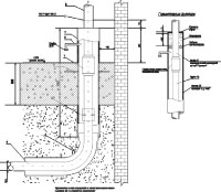
The gas pipeline entering the workshop is usually carried out through the wall of the building in a case (Fig. 5.11). The space between the case and the gas pipeline is covered with a tarred linen strand, and filled with bitumen from the ends. The case is designed to protect the pipeline from damage during minor seasonal or other wall deformations. Directly at the gas pipeline inlet, a general disconnecting device (valve, valve) is installed in a serviceable and illuminated place. Gas pipelines in workshops are laid openly on walls, columns and other structures in places convenient for maintenance and excluding the possibility of their damage by workshop transport. It is not allowed to lay gas pipelines through basements, rooms of explosive industries, warehouses of explosive and combustible materials, rooms of electrical distribution devices and substations, ventilation chambers, and also through rooms in which the pipeline will be subject to corrosion (pouring, slag, preparation, etc.). Gas pipelines should also not be laid in the area directly affected by the thermal radiation of the furnaces, in places where they can be washed with hot combustion products or in contact with hot or molten metal.
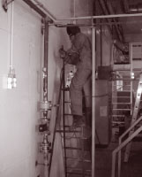
Gas pipelines are fixed with special metal brackets or pendants with clamps. When the valves are located at a height of more than 2 m, observation platforms with stairs are arranged or a remote drive is provided. If fittings are used occasionally, maintenance personnel can use ladders. The distances between the gas pipelines and the walls of the workshop are selected on the basis of ensuring easy inspection and repair of gas pipelines, flange connections, fittings and equipment. In the places of passage of people, gas pipelines should be laid at a height of at least 2.2 m, counting from the floor to the bottom of the pipe.
In workshops and boiler rooms, as a rule, gas pipelines are laid above ground. When the heat generating units are located in places where it is impossible to supply elevated gas pipelines, it is allowed, as an exception, to lay them underground in concrete channels with upper removable plates. The dimensions of the channels are selected based on the possibility of installation and ease of use. The free space between the channel and the gas pipeline is covered with sand to eliminate the possibility of gas accumulation. When providing permanent ventilation, the channel with the gas pipeline can not be filled with sand. Gas pipelines in the channels must have a minimum number of welded joints. Threaded, flange connections, as well as the installation of valves in the channels are prohibited.
Fig. 5.16. Gas pipeline input unit.The gas pipelines at the final remote sites are equipped with purge gas pipelines designed to release gas pipelines from the air before starting the heat generating units and displacing the gas with air during repair, preservation or long-term shutdown of the gas supply system. Purge gas pipelines of units (furnaces, boilers, dryers, etc.) can also be connected to workshop purge gas pipelines. Blowdown pipelines are led out of buildings and laid on the outer surface of the walls at least 1 m above the eaves of the roof, in a place where the gas is safely dispersed. To exclude the possibility of precipitation, the end of the pipeline is either bent or a protective umbrella is mounted on it.
Pipes are connected by gas welding. Threaded and flange connections are allowed in the places of installation of fittings, GRU equipment, instrumentation, gas burners.

Gas pipelines. The choice of piping scheme for thermal units (boilers, industrial furnaces, dryers, etc.) depends on the unit's thermal capacity, type and number of burners, gas pressure in the system, type of disconnecting devices (taps or valves), and the type of automation system used regulation and safety. It has been proven over many years that by the reliability of shutdown (tightness), taps and valves are more efficient than gate valves. Even a small gas leak is immediately detected by smell, since gas flowing through an oil seal or plug usually enters the room, and not into the furnace. The insufficient density of the valve leads to significant gas leaks into the furnace, and it is almost impossible to detect these leaks without special devices.
The variants of the piping piping schemes are very diverse and are strongly tied to the types of units, their design, the internal equipment used (gas burner devices, automation units, disconnecting and metering devices). Therefore, in each situation, their own schemes adapted to local conditions should be developed.
Safety explosive valves. The greatest pressure during the explosion of a gas-air mixture in confined volumes reaches 1 MPa (10 atm) (Table 5.18). Most of the elements of the building envelope collapse at a pressure of up to 0.05 MPa: brick walls 51 cm thick collapse at a pressure of 0.050 MPa, 38 cm thick - 0.020 MPa, and glazed window openings at only 0.002 MPa. An explosion of a gas-air mixture in furnaces and flues leads to instantaneous adiabatic expansion of combustion products and an increase in pressure, which can destroy the building envelope of a thermal installation. The formation of explosive gas-air mixtures can occur when gas leaks through the valve, the extinction of the burner flame during operation, etc. Even small gas leaks are dangerous, since the volumes of the furnaces and gas ducts are relatively small.
To prevent the destruction of the enclosing structures of the furnaces and flues of thermal installations, safety explosive valves are installed that operate at pressures lower than the destructive structures of pressure installations. These valves provide timely pressure relief of the combustion products from the chamber where the explosion occurs.
The most widely used valves are bursting, folding and relief types installed on the ceilings and walls of the furnaces and gas ducts. Valves are installed in areas of the most likely accumulation of gas leaks, the formation of gas bags. They must be positioned so that when the blast wave is not triggered, maintenance personnel are not affected. If this is not possible, it is necessary after the valve to equip a protective box or visor, firmly attached to the unit and diverting the explosive exhaust to the side. The shape of the blasting valves should be square or round, since in this case less pressure is required to rupture the membrane.
The burst valve has a membrane of sheet asbestos with a thickness of 2-3 mm, which is destroyed by an explosion. Through the hole formed, the combustion products are discharged into the environment. To increase strength and durability, a metal mesh with cells of 40x40 or 50x50 mm is mounted in front of the membrane from the furnace side. Asbestos sheet and mesh are clamped with flanges that attach to metal boxfirmly mounted in the lining of the thermal unit. It should be noted that the asbestos sheet can operate for a long time at temperatures up to 500 ° C, so the explosive valves are installed so that the asbestos membrane is not exposed to heat from the torch and incandescent masonry. Explosive valves are simple and inexpensive.
In the hinged valves, in the event of an explosion in the furnace, the valve opens and releases an opening for the emission of combustion products. On the side of the furnace, to prevent overheating, the valve is lined with a solution of refractory clay with asbestos along a reinforcing metal mesh. When closed, the flap valve is sealed around the perimeter with refractory putty.
Relief valves are a panel laid horizontally and discarded in the event of an explosion. Depending on the installation location and temperature conditions, the discharge panel can either be made of asbestos sheet with a thickness of 8-10 mm, laid on a metal mesh and sealed around the perimeter with refractory clay, or from a mixture of refractory clay with asbestos crumb. This panel is reinforced with a metal mesh and can be used at temperatures up to 500 ° C.
Calculation and selection of safety explosive valves is carried out in accordance with applicable SNiP 42-01-2002, “Safety Rules for the Gas Industry” and “Rules for the Design and Safe Operation of Steam and Water Boilers”. In general, it is recommended to focus on the following parameters:
- on 1 m 3 the internal volume of the furnace, gas ducts and hogs should be at least 0.025 m 2 explosive valve, while the minimum surface area of \u200b\u200bthe valve is 0.15 m 2 ;
- explosive valves with a total surface area of \u200b\u200bat least 0.2 m must be installed above the furnace for powerful equipment 2 and on gas ducts - at least two valves with a minimum total surface area of \u200b\u200b0.4 m 2 .
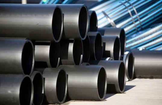
To provide enterprises and the population with natural gas, branched gas supply networks are developed and implemented, consisting of gas distribution points, shut-off, measuring and control valves and pipelines of various pressures. When piping, various pipes for gas pipelines are used.
The use of steel gas pipes
Gas metal pipes are steel (GOST 3262-75) and copper (GOST R 52318-2005). Small diameter copper pipes are used in pipelines of household gas-using equipment, and steel pipes for gas pipelines are used when laying pipelines of various pressures from main pipelines to gas piping for industrial and domestic gas consuming facilities.
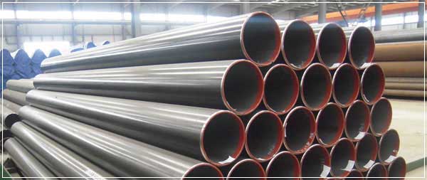
Steel gas pipes with anti-corrosion coating
Depending on the maximum pressure, natural gas transportation pipelines are divided into the following classes:
- high pressure (I and II categories - up to 12 and 6 atm. respectively);
- medium pressure (up to 3 atm.);
- low pressure (up to 0.05 atm.).
Depending on the working pressure, outer diameter, as well as the laying method (external or internal, above-ground or underground), pipes have different requirements for the steel grade, wall thickness, type of anticorrosion coating.
Pipes for gas pipelines are welded in accordance with GOST 31447-2012. The wall thickness is calculated depending on the level of safety of the route in accordance with SNiP 2.05.06-85. Highways are made of pipes for a high pressure gas pipeline. Pipelines of medium pressure are laid to supply apartment buildings and industrial facilities, and low - when supplying gas for combustion in burner devices.
Anticorrosion coating is of the following types:
- galvanizing;
- two or three layer polyethylene;
- anticorrosion paint for thermal insulation.
The degree of protection is determined by the location of the route and the degree of risk in case of violation of the tightness of the walls.
Gas pipes from plastic pipes
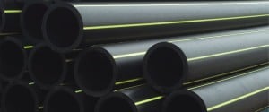
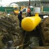
Polyethylene gas pipes marked with a yellow strip of electromagnetic acoustic diagnostics
To provide gas to small settlements in accordance with SNiP 42-01-02 and PB 12-529-03 in category II high pressure pipelines, polyethylene (HDPE) pipes manufactured according to TU 6-19-051-538-85 can be used. For medium and low pressure pipelines, the use of type C pipes is permissible. Plastic pipes for a gas pipeline have restrictions on the use of:
- not applicable in cities and large settlements;
- gas must not contain chlorinated and aromatic hydrocarbons;
- only permitted external underground (deeper than 1 m) pipeline laying;
- seismicity of the laying area - not higher than 6 points;
- air temperature - not lower than 40 ° С;
- soil characterization limitations.
The advantages of polyethylene (HDPE) include low specific gravity and high corrosion resistance, which greatly facilitates assembly and, with proper installation, allows the operation of pipelines for a long period (up to 50 years).

The device of a three-layer polyethylene pipe
Other plastic pipes apply much less frequently or not at all. So, vinyl-plastic ones do not tolerate negative temperatures (the permissible value is minus 5 ° C) and are subject to deformation under loads, and polypropylene ones for a gas pipeline are not used at all due to the high gas permeability.
Design and construction of gas pipelines

Ultrasonic Contactless Scanner
Design and construction of gas pipelines from metal and polyethylene pipes is carried out in accordance with SNiP 2.04.08-87 and SNiP 42-01-2002. These standards determine the gas route diagrams for gas transportation under various conditions and recommendations for the selection of pipes and anti-corrosion coating. The construction of pipelines is carried out strictly according to the developed project and with the implementation of the requirements of SNiPs, safety rules, as well as under the supervision of the general designer.
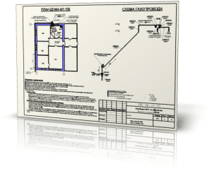
Gas pipeline design, laying scheme
To prevent accidents and technological disasters, gas pipelines are periodically required to be examined. Non-destructive testing methods and equipment for external and internal pipe application are used to test the condition of surfaces. Eddy current and ultrasonic flaw detectors are for external use.

In-line diagnostics of gas pipelines is performed in accordance with GOST R 55999-2014. The most widely used magnetic flaw detector, which not only performs diagnostics, but also cleans deposits from the inside of the pipe wall. If a defect is found, access to the damaged area is opened in a strictly defined place, which is economically advantageous for underground installation. A robotic complex of electromagnetic-acoustic diagnostics has been developed and is already in operation. The diagnostic apparatus inside the pipelines moves on a mobile telecontrol unit.

In-tube magnetic flaw detector
During the development, installation, operation and inspection of gas pipelines, it is necessary to strictly adhere to all regulatory requirements for uninterrupted and trouble-free gas supply to consumers.
Video: Production of steel pipes for gas pipelines at Vyksa Metallurgical Plant
The gas pipeline is designed to transport a combustible mixture belonging to the category of hazardous substances. These circumstances require special materials and network conditions that exclude any leaks. Steel pipes for gas pipelines have been used from the beginning of widespread gasification to the present day. And although their plastic counterparts appeared on the modern market, they still could not replace traditional products, despite the fact that they have a number of advantages.
What are steel pipes and gas pipelines
Different types of pipes are available for gas pipeline networks. They can be divided into two main groups:- seamless
- welded.
The first group consists of hot and cold-deformed, and the products of the second group differ in the type of seam - straight or spiral. In the manufacture of pipes, different grades of carbon steel are used, specified in GOST 380-2005. The use of one or another chemical composition of steel, the type and size of gas pipes depends on several factors:
- system pressure - high, medium, low;
- pipeline locations - above ground, underground, under water, in a building;
- network destination - backbone, distribution, backup.
Main gas pipelines are divided into two categories. They transport explosive mixtures under pressure up to 10MPa over considerable distances. In this case, steel pipes of large diameters are used, to which the highest demands are made.

Distribution networks deliver gas directly to the points of analysis, that is, to the consumer. Such pipelines have a smaller diameter and thinner walls. There are various nuances. For example, a gas pipe can be laid in apartments - steel or plastic in the form of a flexible hose.
Regarding the backup network, we can say that it is intended for special purposes - strategic. Increased requirements are imposed on it, since in certain situations it may not be used.
Gas pipes must have a certificate and related documents that indicate the manufacturer and information about the tests performed, the production method and grade of steel, a mark of conformity and GOST number.
Sorting Standards
GOST 3262-75
This standard relates to the production of gas and water pipes intended for the installation of distribution systems supplying natural gas under high pressure (up to 1.6MPa). The nominal diameter of the products is up to 150mm, length - from 4 to 12 meters.
GOST 8734-75
The regulatory document indicates the assortment of seamless pipes made by cold forming. They withstand pressure up to 10MPa. The maximum size of the outer diameter is 250mm. Measured length varies from 4.5 to 9 meters.
GOST 8732-78
It also determines the assortment of seamless pipes, but not cold, but hot-deformed. Their outer diameter is large - up to 530-550mm with a wall thickness - up to 75mm. Products are delivered in a length of 4-12.5 meters. Pipes may be installed on high pressure gas pipelines.
GOST 10704-91
The standard specifies the assortment of electric-welded straight-line pipes. Their outer diameter can reach 1420 mm. The length of products depends on their diameter. It varies from 2 to 12 meters.

Advantages and disadvantages of steel gas pipes
The positive characteristics of the products include:
- sufficient strength;
- slight linear expansion;
- ability to withstand high pressure;
- one hundred percent tightness with proper docking and no defects.
Negative sides:
- the possibility of condensation due to high thermal conductivity;
- high probability of corrosion processes;
- lack of flexibility;
- laborious installation using welding.
Installation requirements
Laying gas pipelines provides for compliance with certain rules:
- the design position must be strictly observed;
- the connections must be performed in a quality manner to prevent gas leaks during operation;
- pipes should be mounted so that they fit snugly to the base;
- the safety of factory anticorrosive insulation is an important technological moment, on which the immunity of steel walls to the influence of stray currents, as well as the absence of rusting processes, depends;
- welds are subject to mandatory treatment with bitumen-based compounds.
The insulation of gas pipes intended for laying in the ground is made in the factory. Its high-quality implementation at the construction site is impossible due to the technological features of the process. Depending on the ground conditions, the protective coating can be normal and reinforced.
Gas supply is one of the most important issues to be considered during the construction and improvement of a private house. However, this task falls not only on the shoulders of the owners, but also on specialized services, since laying a gas pipeline and connecting it is a problem exclusively for such services.
With all this, it is necessary to know the classification of gas supply systems, as well as the classification of the individual components of such systems. For example, what kind of gas pipes can be, so that you can correctly express your wishes in this matter.
What are the gas pipelines
All gas pipelines are divided into several types, depending on the pressure that they experience. According to this indicator, the following types can be distinguished:
- High pressure. In them, it can range from 0.6 to 1.2 megapascals. These systems fall into the first category;
- High pressure with operating indicators from 0.3 to 0.6 MPa. These systems fall into the second category;
- Medium pressure with operating indicators from 0.005 to 0.3 MPa;
- Low pressure with indicators from 0 to 0.005 MPa.
It must be said right away that the material from which the gas pipe should be made depends not only on pressure, but also on many other factors. Strictly speaking, pressure is generally small, which depends, since modern industry even produces plastic pipes capable of competing with metal in this parameter.

In general, gas pipes in a section can be selected based on the following factors:
- The situation of the village;
- Soil characteristics;
- Aggressiveness of stray currents and many others.
What are the pipes
Now, knowing what gas supply systems can be, we should proceed to consider their individual components - pipes. Gas pipes used to be represented by only one material - steel. Today, as already noted, the industry also produces polyethylene gas pipes. At the same time, in terms of their operational characteristics, they are not much inferior to metal ones.
Overview of Plastic Products
Gas pipes on the site, made of plastic, are characterized by a high degree of resistance to various atmospheric precipitation. In addition, in chemical terms, they also show excellent stability.
Home plastic products are quite durable. Therefore, they can easily be used in open areas and even in very harsh climatic conditions. They are able to maintain all their positive qualities even at very low temperatures - up to -60 degrees.
Another great advantage of plastic can be considered that it is not afraid of stray currents, since polyethylene itself is not a conductor.
Among other things, it should be noted that all pipes made of polyethylene do not need any additional protection, since they are not afraid of moisture, unlike steel products.
Another important advantage is the cost. It practically does not differ from the cost of steel products.
Important! With all these positive qualities, only metal pipes are recommended in the house itself, but polyethylene can also be put into the ground.
In a general sense, restrictions on the use of these products are as follows:
- It is not recommended to use polyethylene in areas where the temperature may drop below 45 degrees;
- Do not lay plastic products in areas where seismic activity can reach more than 6 points;
- Also, plastic is not used in the city, where the main gas pipeline belongs to the first or second category, that is, it has very high pressure;
- Such products are not used for the installation of pipelines underground and on the ground, as well as inside the house, as already mentioned, inside tunnels and collectors.
In all these cases, only steel pipes can be used.
Steel products
It’s worth saying right away that all steel materials are subject to electrochemical and anti-corrosion treatment. This will significantly increase their life. Due to this, the cost of the entire structure increases significantly, compared with the cost of the construction of plastic elements.

I must say that such materials have their own classification, as they have been produced for a very long time. First of all, the division into types is carried out by the presence of welds:
- Welded;
- Seamless.
All such materials can be made from a mixture of mild steel and structural steel. stainless steel. Among other things, there are such additives:
- Sulfur, about 0.056%;
- Phosphorus, about 0.25%;
- Carbon, about 0.046%.
The guest has established that the wall should have a minimum thickness of about 3 mm, if we are talking about materials that are intended for underground work, and at least 2 mm for those materials that are intended for ground work, or work inside the house.
From this point of view, the following important characteristics can be distinguished:
- Wall thickness;
- Nominal diameter
- The diameter of the gas pipe or the sum of the first two parameters.

So, steel pipes, like plastic ones, depending on the withstand pressure can be divided into three categories:
- For laying underground with a working pressure of up to 1.2 MPa. In this case, the outdoor temperature can reach -30 degrees;
- For work on soil with a working pressure of up to 1.2 MPa. In this case, the outdoor temperature should not be lower than -10 degrees;
- For installation inside the house with a working pressure of up to 0.3 MPa. Moreover, the outer diameter of such products does not exceed 15.9 cm. The wall thickness is about 5 mm. The temperature of the product during operation should not be lower than 0 degrees.
It should be noted that all gas pipes must undergo anti-corrosion treatment. In most cases, this treatment consists in coloring in a characteristic bright yellow color.