When assembling horizontal joints of pipes for welding, on the bottom pipe it is not necessary to perform the complete cutting edge. It is allowed to make only a small cutter, a value of 10 °. This reception improves the process of welding metal, while not reducing its quality (see scheme A) in the figure below). When preparing non-responsible pipelines to welding, the edge on the bottom pipe is often not separated at all (see the scheme b) in the figure below).
The most good results are obtained when welding horizontal joints of pipes with separate narrow layers. The first roller boil the root of the seam (see the C) scheme in the figure below), for this, the electrodes with a diameter of 4mm are used. The current strength is set in the range of 160-190a. The electrode is reported to reciprocating movement, while on the inside of the joint should form a thread roller, a height of 1-1.5 mm.
After the overlay of the first layer, its surface must be carefully cleaned. The second layer is carried out with the accounting for it to overlap the first layer with a reciprocating movement of the electrode and with its slight fluctuations from the edge of the lower edge to the edge of the upper edge. The welding of the second layer is performed in the same direction as the welding of the first layer.
After performing the second layer, the power of the welding current is increased to 250-300a and the third layer is performed. Welding is carried out by electrodes with a diameter of 5mm, this allows you to increase the performance of the welding process. The supply of the third layer should occur in the direction opposite to the welding of the first two layers. The third roller must overlap 2/3 of the width of the second roller. The filming of the fourth roller occurs in the same direction, but it should be located in the recess of the third roller and the upper edge.
When welding horizontal junctions of pipes more than three layers, each subsequent layer, starting from the third, should be performed in the direction opposite to the previous one. Pipes whose diameter does not exceed 200mm, usually welded with solid seams. If the diameter of the welded pipe exceeds 200mm, then the welding is performed by a backstage method.
Video: Welding of pipes with horizontal junction
Welding of non-turning jacks
Vertical non-turning junctionsweld up upwards.
The welding of the first three layers in the joints of the pipes with a diameter of more than 219 mm should be carried out in a renewable method. The length of each site should be 200-250 mm.
The length of the sections of the subsequent layers can be half the circumference of the joint. Pipe joints with a thickness of the wall to 16 mm can be welded with a length of the half of the circumference, starting from the second layer.
Priority of seams (1-14) and layers (I-IV) by one welder
| Second stage |
 |
Horizontal non-reflective jointsthe pipes with a diameter of more than 219 mm, performed by one welder, it is necessary to weld in the renewable method of sections with a length of 200-250 mm. The fourth and subsequent layers can be welded.
Priority (1-12) performing seams by one welder
When welding a horizontal joint with two welders, the welding sequence of the root seam depends on the diameter of the pipes. If the diameter is less than 300 mm, then each welder brews a half of the circumference. In the same time, welders must be in diametrically opposite joint points. If the diameter of pipes is 300 mm and more, then the root seam is welded with an invertible method of sections of 200-250 mm.
 |  |
||
In the joints of the pipes with a diameter of up to 300 mm with a wall thickness of more than 40 mm, the first three layers should be welded in a renewable method, and the subsequent layers are areas equal to half of the circle.
The joints of the pipes made of low-alloyed steel with a diameter of over 600 mm with a wall thickness of 25-45 mm are welded as follows: All seam layers are performed with a renewable method by plots of no more than 250 mm.
Pipes with a diameter of more than 600 mm from chromolibdenovadium steel, two and more welders are welded simultaneously, each of which has its own segment of the joint. Apply an inverse method (sections of 200-250 mm). The fourth and subsequent layers are allowed to perform sections equal to a quarter of the circle.
Priority and approximate location of layers and rollers (1 - 20) when welding vertical and horizontal joints of thick-walled pipes from carbon and low alloy steels
Manual technique arc welding pipes covered electrodes
Welded seam is performed for two receptions. The perimeter of the junction is conditionally divided by a vertical axial line into two sections, each of which has three characteristic positions:
Ceiling (position 1-3);
Vertical (position 4-8);
Lower (position 9-11). Each plot is welded from the ceiling position. Welding is carried out only with a short arc:
where D is the diameter of the electrode. End the seam in the lower position.
The welding of each of the sections begin with a displacement of 10 20 mm from the vertical axial. The seam overlap section is the "lock" compound - depends on the pipe diameter and can be from 20 to 40 mm. The larger the diameter of the pipe, the longer the "castle"
The initial section of the seam is performed in the ceiling position "angle back" (pos. 1,2). When moving to a vertical position (pos. 3-7), welding is "angle forward". Upon reaching the position 8, the electrode is oriented at a right angle, but by going to the lower position, the welding again leads the "angle back".
Before welding the second site you need to clean the initial and final sections of the seam with a smooth transition to the gap or to the previous roller. The welding of the second site should be performed in the same way as the first one.
For root seam used electrode with a diameter of 3 mm. The strength of the current in the ceiling position 80-95 A. The current vertically is recommended to reduce to 75-90 A. during welding in the lower position of the current increase to 85-100 A.

When welding pipes with high-quality formation of the root of the seam without a fitting, the carrier is achieved by constant feeding the electrode into the gap. To achieve the regulation inside the pipe, you can get a seam with a convex surface, which will require the subsequent mechanical stripping in the ceiling position.
Filling the cutting of pipes with a wall thickness of more than 8 mm occurs unevenly. As a rule, the lower position is lagging behind. To align the cutting of the cutting, it is necessary to additionally remake the rollers at the top of the cutting. The penultimate layers must leave the blank on the depth of no more than 2 mm
 |
Facing seams are welded for one or more passages. The penultimate roller finish so that the cutting remains unfilled to a depth of 0.5-2 mm, and the main metal along the edges of the cutting was cleared on the width of 1/2 of the diameter of the electrode.

When the pipe welding with a diameter of less than 150 mm with a wall thickness is less than 6 mm, as well as in the installation conditions, when the power source is removed from the place of operation, the welding is carried out at one and the same welding current value. It is recommended to select the current mode on the ceiling position, the current in which is sufficient for the lower position. When welding on a rise from the ceiling position to vertical, so that there is no excessive regulation, it should be resorted to intermittent seam formation. In this case, the method is periodically interrupting the process of burning arc on one of the edges.
Depending on the thickness of the wall of the pipe, the gap and dull edge, it is recommended to perform welding with "smears" by one of the ways:
1. ignite the arc constantly on one of the edges, and break down after the formation of the bath - to another. The pause between the cliff and the ignition should be so short that the metal seam does not have time to fully crystallize, and the slag is cool.
2. With a large metal thickness, the arc is lit on the same edge.
Ignition of arc coupling arc
Welding of a non-turn horizontal joint
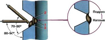
Welding with the formation of stable regulation is conducted by an electrode with a diameter of 3 mm. The welding current is chosen depending on the thickness of the base metal, the gap between the edges and thickness thickness. The slope of the electrode is 80-90 ° to vertical. When welding a "angle back", the slope provides maximum inqualing, and the "angle forward" is minimal.
In case of insufficient regulation, the length of the arc should be kept short, and with normal carriage - medium.
 |  |
||
The root seam is better to perform with minimal sizes of the welding bath so that there are no feeds and springs on the reverse side of the seam.
Second rollerformed so to melt the first root seam and both edges of the pipe. The welding current is installed on the average range. The slope of the kettle is the same as when welding the first root seam. Welding lead the "angle back". The speed is chosen so that the appearance of the roller is normal (not convex and not concave)
Third rollerit is better to perform at increased modes. Welding lead at a right angle or "angle back". The speed is chosen so that the roller is convex, with a shelf to hold the metal bath of the subsequent roller. The arc trajectory should coincide with the edge of the second roller.
Fourth roller- horizontal. It is performed on the same modes as the third one. The electrode is tilted at an angle of 80-90 ° to the vertical surface of the pipe. The welding speed is supported so that the top edge of the cutting is melted, the surface of the second roller and the top of the third roller. Appearance The fourth roller must be normal.
 |
"Castle» connectionsit is welded with a smooth increase in the seam size at the beginning and a decrease in the final section, "raid" to the beginning of the seam by 20-30 mm.
Welding facial layerit is necessary to perform electrodes of the same diameter, which were used when filling the cutting, but not more than 4 mm. The last top roller is laid at a higher speed so that it turns out to be narrow and flat
Technology hand argon-arc welding pipes
Technological options
Welded seam is completely performed by manual argon-arc welding with a non-compatible electrode (it is recommended at the thickness of the wall to 3 mm);
The welded seam is performed by a combined method: root seam - manual argon-arc welding with a non-compatible electrode, and the subsequent layers - manual arc welding with a coated electrode (it is advisable at the thickness of the pipe wall 4 mm or more).
Approximate location of layers and rollers (1 - 8)
 |
In the joints, cooked according to various technological options
With the wall thickness of up to 2 mm, the joint cross section should be welded into one layer
Manual argon conversion welding of a non-compassion W-electrode is used for non-reflective joints of pipes from low carbon, low-alloyed and alloyed (corrosion-resistant) steels. The diameter of the welded pipes is less than 100 mm, the wall thickness is up to 10 mm.
Select mode parameters
Welding currentchoose: with single-pass welding - depending on the thickness of the pipe wall, and with a multi-frequency - based on the roller height, which should be 2-2.5 mm. The welding current is prescribed at the rate of 30 - 35 A per 1 mm diameter of the electrode.
Tension on the arcit should be minimal, which corresponds to the welding of a short arc.
Welding speedregulate so that the edges are guaranteed and the formation of the desired seam sizes.
Protective gas consumptiondepends on the brand of welded steel and current mode (from 8 to 14 l / min).
Front wirea diameter of 1.6-2 mm is chosen along the brand of welded steel (see table on p. 16).
To categoriarity: Welding work
Manual electric arms welding of pipeline joints
For manual electric arc welding of pipes, metal electrodes are used, which serve as an additive material for filling welded seam And at the same time the current conductor to the arc.
The quality of the weld depends largely on the state of the coiled surfaces of the pipes, on the accuracy of the combination of their ends and mainly from the electrode used, which is a metal coated metal rod. The metal rod of the electrode is made of different thickness electrode wires. For welding pipes, a wire is used with a thickness of 2 to 5 mm.
Electrode coatings are thin and thick, the last with high-quality coating. The coating of the electrode with a subtle (chalk) coating is 1-2% of the weight of the metal rod. The cooler of the high-quality electrode is 20-30% of the weight of the metal rod.
The most important property of the coating-forming slag. Slag is a non-metallic alloy whose share is less than the specific gravity of the welded metal; The slag floats up and creates a mechanical cover of molten metal. The slag protects the molten metal from the absorption from the chopped environment of harmful gases for seam - oxygen and nitrogen.
Since the slag melts at a lower temperature than the main metal, and during solidification is made fragile, then the welder easily resets it with a thickness of the weld of the rod of the electrode. The sewing sew is a defect of electric pipe welding, because any non-metallic inclusions dramatically reduce the strength of the seam.
Thin (chalk) The coating consists of 80-85% of the chalk and 15-20% of liquid glass, which is a binder material, due to which the coating is held on the rod. Thin coating is needed for continuous burning of the arc, since frequent arc breaks worsen the quality of the weld.
U.Electrodes with a thick coating of the arc burning stable, but the metal deposition occurs under the slag layer, which prevents seeing the formed seam. The strength and viscosity of the seam is significantly higher than that of the seams performed by electrodes with fine coating. Improving the quality of the seam is achieved by the protection of the metal on the action of oxygen and nitrogen of the air formed by a slag from thick coat of the electrode, as well as the introduction of high-quality elements into the reducible metal. These elements are moving from coating in the metal during welding.
For manual arc welding of pipes, it is necessary to use E-42 and E-42A electrodes. Electrodes must have a coating of the same thickness of software. All electrodes without cracks, local thickens and other visible defects.
The diameter of the electrode should be chosen depending on the thickness of the coiled pipes. Button connections Pipes with a thickness of the wall - up to 5 mm need to be welded by electrodes with a diameter of 3 mm at a current for rotary joints at 100-250 A, and for non-turning joints-80-120 a.
In multi-layered button seams The first layer must be performed by an electrode with a diameter of 4 mm to provide a deep provider, subsequent seams - with electrodes of greater diameter.
Welding wires that supply current from the power supply to welding argemust be lightweight, flexible and have reliable insulation.
When welding, the following types of connections are performed: jack, tweeted, vtavr and angle.
The compound of the pectorist is called this, in which one element is superimposed on another. The width of the latter itself should be at least two metal thicknesses.
According to the position in which the welding is produced, the seams are lower, horizontal, vertical and ceiling. Lower seam is most convenient for welding. It is located at the bottom under the electrode, and the welding is made from above. Horizontal seam Perform the circumference of the pipe installed vertically. Vertical seam is located on the side of the installed steep pipe, welded by its length. Ceiling seam Performed above the welder's head.
Welding pipelines is better in the lower position (swivel seams). Only closing mounting joints perform non-reflective.
Steel tubes Connect predominantly jack. The connection of pipes. The word requires the mandatory provision of edges to the entire thickness of the walls.
Types of electric arc welding of small diameter pipes are shown in Fig. one.
To reduce the influx inside the pipe, the angle of inclination of the electrode to the horizontal should be no more than 45 ° (Fig. 1, a).
When welding the butt and T-shaped compounds of the pipes of small diameter, the electrodes with a diameter of 3 mM of type E-42 and E-42A are used (Fig. 1, b, d). The strength of the current is set to 80s. The weld should have a height of 2-3 mm, a width of 6-8 mm.
When welding, the same electrodes apply the same electrodes when welding; The current strength is set to 10Q-120 a. The height of the weld must be 3 mm, and the width is 6-8 mm.
Before welding pipes, the following preparatory work must be performed: - Clean pipes from soil, dirt and garbage; - Crop or straighten the deformed pipe ends. The straighted ends of pipes must match when they are aligned. The presence of dents and calas is not allowed;
In arc welding, clean the edge to the metal brilliance and adjacent to them the inner and outer surface of the pipes on a width of at least 10 mm;
joints of the joints to perform without a break in operation until the whole joint is fully welding; - welding pipelines without lining rings; - arc welding of rotary and non-reflective joints of pipes with the thickness of the walls to B mm to perform at least two layers; With the thickness of the pipe wall from 6 to 12 mm - in three layers and with a thickness of 19 mm and higher - in four layers. Each seam layer before overlaying the subsequent should be cleaned of slag. The first layers of the RVA should provide a complete provider of his root.
Fig. 1. Electric welding of pipes: A - position of the electrode when welding pipes, b - welding of pipes for jacking, in - Welding pipes of the Vansel, G - Welding of pipes during branches
The shape of the edges of the pipes and the angles of their bevel used during welding must correspond to the values \u200b\u200bshown in Table. one.
Table 1
The shape of the edges of pipes prepared for welding 
Manual arc welding of pipes with a thickness of the wall up to 4 mm and automatic welding of pipes with a thickness of the wall up to 6 mm inclusively produce without a bevel of edges.
Deviations from the alignment (displacement of the edges) when assembling pipes should not exceed the values \u200b\u200bgiven in Table. 2.
table 2
Tolerances of edge displacement A when assembling pipes 
Pipes are harvested with a gap, the value of which is indicated in Table. 18.
Warding nozzles for branches at the location of the welds of the pipeline is not allowed.
The distance between the annular weld of the pipeline and the welding of the nozzle should be at least 100 mm.
Table 3.
Allowable gaps when welding pipes 
The tape should be 40-50 mm long for rotary joints, 60-70 mm for ceiling. The height of the tape should be 40-50% of the pipe wall thickness.
When welding pipes with walls with a thickness of over 8 mm, the first layer is boiled with speed welding, the remaining layers are solid. With stepped welding, the joint circle is broken into several sections, weld at first through the site, and then missed.
The first layer of welding is the most responsible. When you embed this layer, you must completely melt the edges and dullness. Then it is necessary. It is carefully viewed and check if there is no cracks. The detected cracks must be cut down or paid, and the sections are again welded.
The second and third layers are welded, slowly turning the pipe. The beginning and end of each of these layers should be shifted by 15-30 mm in relation to the beginning and end of the previous layer.
The last seam should have a smooth surface and smoothly move to the main metal.
In case of multilayer welding, each subsequent layer is carried out in the direction of the reverse preceding, the closing sections of each layer have a rotary side relative to each other. This improves welding quality.
After welding of each layer of seam and the area adjacent to it is purified from slag and splashes for better fusion of the layers.
Manual electric arms welding of pipeline joints
Chapter XXVIII.
Features of welding some types of structures
§ 125. Pipe welding
General. When building pipelines, welded joints can be swivel, non-reflective and horizontal (Fig. 123).
Fig. 123. Welded pipe joints:
and - swivel, b - non-turn, in - horizontal
Before assembling and welding the pipe, they check for compliance with the requirements of the project, according to which the pipeline is constructed, and specifications. Basic Requirements: The presence of a certificate on pipes, the absence of pipe ellipsence, the absence of pipe size, compliance of the chemical composition and mechanical properties of the pipe metal with the requirements specified in technical specifications or GOSTs.
In the preparation of joints of pipes for welding, the perpendicularity of the plane of the pipe cutting to its axis is checked, the angle of the edge of the edge and the magnitude of the dullness. The seam disclosure angle should be 60-70 °, and the magnitude of the recess is 2-2.5 mm (Fig. 124). The champers are removed from the ends of the pipes by mechanical method, gas sharp or other methods that provide the required shape, dimensions and quality of the treated edges.

Fig. 124. Preparation of pipe edges for welding with wall thickness 8-12 mm
The difference in the thickness of the walls of the coiled pipes and the displacement of their edges should not exceed 10% of the wall thickness, but be no more than 3 mm. When docking pipes, a uniform gap between the connected edges of the juggled elements is 2-3 mm.
Before assembling the edge of the jammed pipes, as well as the inner and outer surfaces adjacent to them at a length of 15-20 mm are purified from oil, scale, rust and dirt.
Phacks that are an integral part of the weld, perform the same welders that will weld the joints using the same electrodes. When the pipes are welding with a diameter of up to 300 mm, the tag is performed evenly around the circle in four places with a height of 3-4 mm and 50 mm long. When welding pipes with a diameter of more than 300 mm, the tapes are uniformly throughout the entire joint circle every 250-300 mm.
When installing pipelines, it is necessary to strive to ensure that more junctions are welded in a swivel position. Pipes whose wall thickness is 12 mm, welded in three layers. The first layer creates a local province in the root of the seam and reliable fusion of the edges. To do this, it is necessary that the filtered metal formed inside the pipe a narrow thread roller with a height of 1-1.5 mm, evenly distributing throughout the circle. To obtain a provider without icicles and graph, the movement of the electrode must be reciprocating with a non-losing electrode delay on a welding bath, a slight transverse oscillation between the edges and the formation of a small hole at the top of the angular angle of the edges. The hole is obtained as a result of the propagation of the main metal by the arc. Its size should not exceed 1-2 mm set gap between pipes.
Welding swivel joints. The first layer of 3-4 mm height is welded with electrodes with a diameter of 2, 3 and 4 mm, the second layer is filmed with a larger diameter electrodes and with an increased current. The first two layers can be performed in one of the following ways.
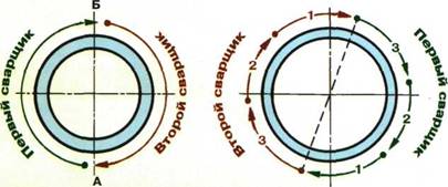
1. The joke is divided into four sections. Initially, the sections 1-2 are welded, after which the pipe is rotated 180 ° and the sections 3 and 4 are brewing (Fig. 125). The pipe is then rotated by another 90 ° and welded sections 5 and 6, then rotate the pipe 180º and weld sections 7 and 8.

Fig. 125. Pipe joint welding circuit:
2. The joke is divided into four sections. First weld 1 and 2, then rotate the pipe 90 ° and the sections 3 and 4 are welded (Fig. 126). After welding of the first layer, the pipe is rotated by 90 ° and the sections 5 and 6 are welded, then the pipe is 90 ° and the sections 7 and 8 are welded.

Fig. 126. Scheme of the joint of the pipe on the second method
3. The joint is divided into several sections (when welding pipes with a diameter of more than 500 mm), welding lead the retrain-step in the individual sections (Fig. 127). The length of each seam section (1-8) is 150300 mm and depends on the diameter of the pipe.

Fig. 127. Scheme of welding of the joint of large diameter pipes:
a - first layer, b - second layer
The third layer in all methods discussed above are applied in one direction when the pipe is rotated. On pipes with a diameter of up to 200 mm, you can not divide the joint to the sections and weld it with a solid seam with turning the pipe in the welding process (Fig. 128). The second and third layers are performed similarly to the first, but in opposite directions. In all cases, each subsequent overlapping by the previous 10-15 mm is necessary.
Fig. 128. Small diameter tube joint
Welding of non-turning junctions. Non-turning joints of pipes with wall thickness up to 12 mm are welded in three layers, the height of each layer should not exceed 4 mm, and the width of the roller should be equal to two-three diameters of the electrode.
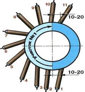
The joints of the pipes with a diameter of more than 300 mm are welded with a reverse step manner, the length of each section should be 150-300 mm, the order of their overlay is shown in Fig. 129.

Fig. 129. Scheme of layers of layers when welding of non-turning joints of diameter pipes up to 400 mm (the numbers of welding sections along the layers are shown, and the arrows - the direction of welding)
The first layer is formed when the electrode is reciprocated with an arc delay on the welding bath. The current is set to 140-170 A, which allows you to pay the edge of the joint to form a narrow thread roller with a height of 1-1.5 mm on its inner side. At the same time, large splashes of molten metal and welding should be made to the welded edges and the welding must be made without burns. For this arc should be short. Opening the arc from the bath, it is impossible to remove it by more than 1-2 mm. The overlap of the beginning and the end of the adjacent layer should be 20-25 mm.
The mode for welding the second layer is the same as for welding the first layer. The electrode during welding of the second layer should have transverse oscillations from the edge of one edge to the edge of another edge.
When welding, the surface of each layer may be concave (Fig. 130, a) or slightly convex (Fig. 130, b), excessive convexity of the seam, especially when ceiling welding (Fig. 130, c), may be the cause of undoubted.

Fig. 130. The surface of the root seam:
and - concave, 6 - slightly convex, B is very convex (the arrows indicate possible places of interest)
To facilitate the observation of the welding zone in the direction of maintaining the last layer of the penultimate layer, apply in the region of edges so that its surface is 1-1.5 mm below the edges of the edges (Fig. 131). The latter layer is performed with a height of 2-3 mm and a width of 2-3 mm greater than the width of the edge cutting; It should have a smooth transition from the weld metal to the main one.

Fig. 131. Edge cutting circuit
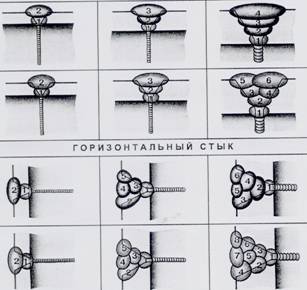
Welding horizontal junctions. When assembling horizontal joints of the pipes, there is no need to completely remove the edges of the lower pipe, it is enough to reveal it at an angle of 10-15 °, which improves the welding process without changing its quality (Fig. 132, a). When assembling invisible pipelines on the bottom tube, the chamfer is not removed at all (Fig. 132, b).

Fig. 132. Cutting diagram of the edges of horizontal joints of responsible (A) and irradicient (b) pipelines and their welding (B), the numbers of layers are indicated.
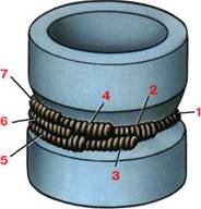
The best welding method of horizontal joints is the welding of small cross-section rollers. The first roller is imposed in the top of the seam (Fig. 132, c) with electrodes with a diameter of 4 mm (at a current of 160-190 A) with a reciprocating movement of the electrode with the mandatory formation on the inside of the joint of the narrow thread roller with a height of 1-1.5 mm. After the first roller (layer), it is cleaned with its surface, the second roller is superimposed so that it overlap the first with a reciprocating movement of the electrode and its small oscillation from the edge of the lower edge to the edge of the upper edge. The welding is performed in the same direction as the welding of the first layer (roller), then the current is increased to 250-300 A and weld the third roller with electrodes with a diameter of 5 mm, which increases the welding performance. The third roller is imposed in the direction opposite to the first, it must overlap 70% of the width of the second roller. The fourth roller is placed in the same direction, but they are in the recess between the third roller and the upper edge.
With the welding of the joint of the pipe in more than three layers, starting from the third layer each subsequent is performed in the opposite direction than the previous one. Pipes with a diameter of up to 200 mm are welded with solid seams, and a diameter of more than 200 mm is a reverse step method.
Dear visitor, you read the article "Welding Pipe", which is published in the category "Manual arc welding". If you liked or useful this article, share it, please, with your friends and acquaintances.
Earn on your knowledge. Answer questions and get money for it!
February 11, 2012 | Views: 48851 |
Array (\u003d\u003e [~ Tags] \u003d\u003e \u003d\u003e 40509 [~ ID] \u003d\u003e 40509 \u003d\u003e Pipeline welding technology [~ Name] \u003d\u003e Pipeline welding technology \u003d\u003e 1 [~ iblock_id] \u003d\u003e 1 \u003d\u003e 115 [~ iblock_section_id ] \u003d\u003e 115 \u003d\u003e
Classification of pipelines
Fishery pipelines
Main pipelines
Water supply and sewage
Welding methods of pipelines
Table 1
Requirements for pipes
In the CIS pipes are used in accordance with GOST 8731 ... GOST 8734 groups B, as well as with the relevant technical and economic justification - according to GOST 9567; Steel electric weld pipes - in accordance with GOST 20295 for pipes with a conditional diameter (DF) to 800 mm inclusive. For Pipe Du\u003e
Pipe assembly requirements
Preheating
table 2
(° C) TP.P \u003d 1440 RCM - 392.
Table 3.
[~ Detail_Text] \u003d\u003e
Classification of pipelines
Depending on the functional purpose of the pipeline, divided into:
Fishery pipelines
Main pipelines
Pipelines Couple I. hot water
technological pipelines
Gas supply pipelines (distribution)
Water supply and sewage
Significant volume in the steel used for the manufacture of pipes and the construction of pipelines of various purposes is occupied by low carbon and low-alloy steel with the yield strength of up to 500 MPa.
Since the technological processes of pipe welding from the indicated steels during the construction of pipelines of various purposes almost little differ from each other, and the governing regulatory and technical documents applied to the differences only in the requirements for the preparation of edges, assembly, quality of welded joints and testing for strength and tightness and tightness In the future, we will consider the general provisions of the manufacturing process on the example of the main and distribution (gas supply pipelines) of pipelines.
Welding methods of pipelines
Methods for welding pipelines are classified as thermal, thermomechanical and mechanical. Thermal methods include all kinds of melting welding (arc, gas, plasma, electron-beam, laser, etc. Types of welding. The thermomechanical class includes butcher contact welding, the welding of the magnetically controlled arc. To mechanical methods include friction and explosion welding.
There are methods for welding pipelines by type of energy carriers (arc, gas, plasma, laser, etc.); under the conditions of the formation of the compound (free or forced formation of the weld); by the method of protecting the welding zone (under flux, in protective gases, using self-protecting electrode wire, etc.); According to the degree of mechanization and automation of the process (manual, mechanized, automated and robotic).
For welding of main pipelines, the greatest distribution received arc methods welding. More than 60% of all joints on the highways are welded by automatic arc welding under the flux. Arc welding under the flux is used only in cases where there is an ability to rotate the joint. The welding of pipelines under the flux is mainly used in the manufacture of two and three-pipe sections with a diameter of 219 ... 1420 mm. When the use of mechanized methods is impossible, manual arc welding is used.
Manual arc welding is performed with various spatial positions of the junction - lower, vertical and ceiling. In the process of welding, manually move the electrode around the junction perimeter at a speed of 8 ... 20 m / h.
Protective gas welding has varieties: according to the type of protective gas - welding in inert gases (argon, helium, their mixture), in active gases (CO2, nitrogen, hydrogen), welding in a mixture of inert and active gases (AG + CO2; AG + CO2 + O2); by type of electrode - melting and uncompaired (tungsten) electrode; According to the degree of mechanization, manual, mechanized and automated welding. Arc welding in protective gases is used for welding by pipeline in various spatial positions. The speed of manual welding 8 ... 30 m / h, mechanized and automated 20 ... 60 m / h. For welding by pipeline, the method of mechanized welding with a powder wire with a forced seam formation is used, in which the protection functions are performed by powdered components that fill the wire shell. As the welding bath is crystallized, the outer forming device and the welding head are moved along the junction perimeter from the bottom up at a speed of 10 ... 20 m / h. Laser welding with a pipeline, in which a laser beam is served by the energy carrier. The speed of laser welding is up to 300 m / h.
When connecting contact welding with continuous melting, the process occurs automatically according to a given program. The duration of the welding of one junction of pipes with a diameter of 1420 mm is 3 ... 4 min, the welding cycle of one joint during the construction of pipelines -10 ... 15 min.
Automatic welding of the magnetically controlled arc (or arcontact welding) differs from the butt contact welding by heating the edges. In the arcontact welding, the heating is performed by an arc rotating the magnetic field along the edges of the coiled pipes at high speed. This welding method is used to construct small pipelines (until 114 mm) diameter.
Regulatory documents used in the construction of main and distribution pipelines
The main regulatory document regulating the rules for the implementation of assembly welding work During the construction of pipelines in the CIS, the "Construction standards and rules" on the basis of which "consolidated rules for the production of welding works and quality control of welded joints were developed" SP 105-34-96, as well as SNiP 3.05.02.88 "Gas supply pipelines". These documents provide rules for qualifying tests of welders and control of tolerance, rules for the preparation of pipes to welding, conditions of editing, repair and rejection of pipes, assembly procedure various pipes with each other and with pipe fittingsThe methods of welding and weather conditions are stipulated when working on the track, regulatory documents regulate the use of recommended welding materials, as well as norms and rules for controlling welded pipeline compounds, conditions for their sejection and repair.
In the development of the main provisions of these SNIPs, technological instructions for welding pipelines were developed (VNI 066-89 and LBN A.3.1.-36-3-96 and the method of controlling welded joints of pipelines (VN 012-88). These instructions regulate: the main provisions of the technology handmade and automatic arc welding of ring joints of pipes, as well as pipes with shut-off and distribution reinforcement of trunk and distribution pipelines with a diameter of 14 to 1420 mm with a thickness of a wall from 1 to 26 mm, designed for pressure not over 7.5 MPa; control of welded joints and their Repair; safety and production sanitation. According to these instructions, it is allowed to weld pipes from steels with regulatory time resistance to 590 MPa inclusive. The instructions present the technological features of pipelines welding using manual arc welding techniques, automatic welding under flux, automatic welding in the protective gases environment and powder wire with coercive seam formation. Instructions do not apply to welding special purpose pipelines (for transporting ammonia, ethylene, ethanol, carbon dioxide, etc.), as well as pipelines for corrosionactive products.
Abroad during the construction of pipelines are guided by national and international standards (Table 1), among which the ARI 1104, ARI 5D and CS 4515 use the greatest popularity. When controlling the quality of pipeline welded connections, as a rule, are guided by international Standard ISO 8517 and the European standard EN 25817.
Table 1
Requirements for pipes
For the construction of trunk and distribution gas pipelines, steel seamless electric welded strawberries and spiralshots are used. Pipes with a diameter of up to 1020 mm are made of calm and semi-luminous low-alloy steels, pipes with a diameter of up to 1420 mm - from low-alloyed steels in a thermally improved or thermomechanically hardened state. Only for distribution gas pipelines low pressure (up to 0.005 MPa) It is allowed to use pipes from boiling low carbon steels.
In the CIS pipes are used in accordance with GOST 8731 ... GOST 8734 groups B, as well as with the relevant technical and economic justification - according to GOST 9567; Steel electric weld pipes - in accordance with GOST 20295 for pipes with a conditional diameter (DF) to 800 mm inclusive. For pipe DU\u003e 800 mm, special technical conditions are developed in which the requirements set out below should be included.
The finished pipes are marked, knocking out stamps (cold stamping) at a distance of 250-500 mm from one of the ends of the pipe the following data: a trademark or name of the manufacturer; The brand of steel or its conditional designation; pipe number; stamp of technical control; Year of manufacture. The plot of sticking is clearly distributed paint. In addition, its diameter and wall thickness indicate on the pipe inshable paint.
Import pipes are manufactured and supplied mainly according to the standards of the American Oil Institute (ARI), such as: AII-5 I (seamless and straight pipes), AII-513 (spiral pipes for various pipelines) AII-51X (pipes for high pressure pipelines) .
According to these standards, pipe steel is combined into groups on the yield strength. Each group of steels with the same yield strength values \u200b\u200bin thousands of pounds per 1 sq. M. According to these standards, there are groups of steels: X-42, X-46, X-52, X-56, X-60, X-65, X-70 with time resistance to destruction from 414 to 565 MPa. The ARI standards in addition to mechanical properties regulate the process of manufacturing pipes, the chemical composition of steel, the size, mass and the length of the pipe, pressure hydraulic tests In the process of manufacture, non-destructive testing methods that are used in the manufacture of pipe repair conditions, etc. The designation of the pipe according to the ARI standard consists of the names of the pipes of pipes, the MONograms of the ARI (trademark meaning that this pipe is made in accordance with the requirements of the ARI), the size of the pipe in inches, the mass of one feet of the pipe in pounds, the designation class of steel and the type of manufacture ( S -Best, e - welded dirt pipes, SW - spiral pipes, P - pipes with longitudinal seam, welded by pressing methods), the designation type of steel (E - steel splashed in electric hollows, M - high-strength low-alloy steel), symptaking species ( Nm -Normalization or normalization and leave, NO - hardening and vacation, NS-High vacation). Marking is performed by indelible paint. Pipes for main pipelines are made of steels with the ratio of the yield strength to the time resistance of the rupture no more: 0.75 - for low carbon steels; 0.8 - for low-alloyed normalized steels; 0.85 - for dispersion-hardening normalized and thermally improved steels; 0.9 - for steels of controlled rolling.
Preparation of pipe edges for welding
Before starting welding and installation work, it is necessary to make sure that the pipes and pipelines are used have quality certificates and comply with the project, technical conditions for their supply. Pipes and details must pass input control in accordance with the requirements of the relevant standards and technical Conditions on pipes.
The ends of the pipes and connecting parts must be in the shape and dimensions of the bevel edges corresponding to the applied welding processes. With their inconsistencies, mechanical processing of edges in the tracks is allowed. For small diameter pipes (up to 520 mm), it is possible to use trails, halves, pipe cutters and grinders. Orbital milling machines, hydroabrasive cutting and grinding machines are used for large diameters. In some cases, when the coils or performing coils are inserted, the use of thermal methods for the preparation of edges, such as:
a) gas oxygen cutting with subsequent mechanical stripping edges by abrasive circle to a depth of 0.1 ..0.2 mm;
b) air-plasma cutting with subsequent machining to a depth of up to 1 mm - due to saturation of the edge with nitrogen (when using argon as a plasma-forming gas, mechanical processing is not required); c) air-arc cutting with a subsequent laying to a depth of 0.5 mm (heading the edges);
d) a rift and cutting with special electrodes of the ANR-2M, ANR-3 or OK.21.03, after which mechanical processing is not required.
Before assembling pipes, it is necessary to clean the inner cavity of the pipes from the soil, dirt, snow there, and also to clean the edge and the inner and outer surface of the pipes and the connecting parts to the width to the width of at least 10 mm.
The plots of strengthening of the external factory seams adjacent to the tube to be weldable, it is recommended to be stuffed to the height of about..d5 mm at a distance from the end of at least 10 mm.
All pipes come on the track from plants with cutting edges intended for manual arc welding with coated electrodes. This cutting (Fig. 1, a) has for pipes of any diameter with a wall thickness of more than 4 mm angle of the bevel of edges of 25-30 ° and dull 1-2.6 mm. With the thickness of the wall 16 mm and the more pipes of a large diameter can be supplied with a combined cutting edge in accordance with Fig. 1, b.
The size depends on the wall thickness and is:
7 mm - with the thickness of the pipe wall 15 ... 19 mm
8 mm - with the thickness of the pipe wall 19 ... 21,5 mm
10 mm - with the thickness of the pipe wall 21.5 ... 26 mm.
Fig. 1. Types of cutting edges of pipes for manual arc welding (A, B), automatic welding in the environment of protective gases (B), automatic welding under flux (g, d, e, g) and powder wire with forced formation (A, B) .
For pipelines Du 1000 mm and over when the appliance of the apparatus root seam is provided from the inside, the cutting presented in Fig.1, B is recommended. During the construction of distribution pipelines, manual arc welding of pipes without cutting edges with a wall thickness of up to 4 mm is allowed. In addition, for pipelines with a diameter of up to 152 mm, it is possible to use gas welding (without cutting edges - up to 3 mm, and one-sided bevel of edges - up to 5 mm).
The connection of the difference pipes on the track is allowed without additional edge processing:
For wall thicknesses, no more than 12.5 mm, if the thickness difference does not exceed 2 mm;
For the thickness of the walls above 12.5 mm, if the thickness difference does not exceed 3 mm. In this case, the shocking edges are not allowed.
The connection of pipes or pipes with shut-off and distribution reinforcement with a larger difference of wall thicknesses are carried out by applying between the jacket elements of the transients of factory manufacture or inserts from the intermediate thickness pipes with a length of at least 250 mm.
It is allowed to perform direct assembly and welding of pipes or pipes with parts of pipelines in different ways up to 1.5 thicknesses with a special processing adjacent to the end of the surface of a thicker pipe or part (Fig. 2, a). Welding of chucks of multiple pipes is not allowed.
The direct connection of pipes with shut-off and distribution reinforcement is resolved under the condition if the thickness of the fitting of the reinforcement does not exceed 1.5 thickness of the pipe wall with the preparation of the reinforcement pipe according to (Fig. 2, b). This preparation must be implemented by the supplier.
Fig. 2. Preparation for welding of tubes and parts with different wall thickness.
Pipe assembly requirements
Build joints of pipes should guarantee:
Perpendicular to the joint to the axis of the pipeline. Deviation from perpendicularity should not exceed 2 mm;
uniformity around the perimeter of the gap, which is within the limits of values \u200b\u200bregulated by the relevant standards and instructions;
the minimum possible range of edges, recorded by universal templates not exceeding permissible values (for trunk pipelines - 0.2 wall thicknesses, but not more than 3 mm, for distribution - (0.15 wall thickness + 0.5 mm);
The mixing of longitudinal factory seams relative to each other at a distance of at least 100 mm - for pipes with a diameter of more than 100 mm and 1/3 of the circle length - for pipes with a diameter of less than 100 mm. In the case of the technical impossibility of performing these requirements, additional ultrasonic monitoring of the welding compound is prescribed on this section of the joint.
In the manufacture of pipes of large diameter, the cylinder housings from the shells apply the following types of assembly and welding - "Assembly and welding of housing shell."
Preheating
Preheating is one of the most important technological operations that allow you to adjust the thermal welding cycle. It is known that the structure and properties of the welded joint are largely determined by the speed of cooling the metal in the temperature range of 800-500 ° C (the lowest resistance of austenite). At high cooling rates, the formation of martensite-type hardware structures is possible, which have high strength and low plasticity, as well as a tendency to form cold cracks. This is especially true of low-alloyed steels with carbon equivalent of 0.43% and higher. These steel became very sensitive to the action of the thermal cycle, to concentrators, and the thermal influence zone is prone to embrittlement. These phenomena are most clearly manifested with manual arc welding, when the cooling rate of the GVT metal can reach 70 ° C / s. With a given thickness of the pipe wall, adjust the cooling rate of the thermal influence zone can be changed by the initial temperature of the connecting edges of the preheating. It is especially important when welding the root of seam with cellulose coating electrodes, when the cooling rate is maximum compared with the welding of other seam layers, the rowing welding energy is reduced (welding speed by such electrodes twice the welding speed of electrodes with the main coating) and increased the tendency and formation of cold cracks for An account for an increase in the content of diffusion hydrogen in the weld metal. Preliminary heating not only reduces the likelihood of the formation of hardening structures in the GVT, but also creates conditions for the active evacuation of diffusion hydrogen from the weld metal and the specified zone. What, in turn, increases the resistance of welded compounds against the formation of cold cracks, especially when using electrodes with a cellulose coating, when the hydrogen content in the seam can reach 50 mm per 100 g of the weld metal.
The temperature of the preheating is chosen depending on the chemical station (by carbon equivalent), the thickness of the pipe machines, ambient temperature and the type of electrode coating. These parameters are usually governed by the relevant standards and technological instructions. So, for example, in the CIS are guided by VNC 066-89 (Table 2). When welding with electrodes with cellulose coating, the temperature of the preheating increases by 75 ° C.
table 2
Abroad, often, when selecting heating, operate with an indicator of the crack resistance of welded joints, determined by the formula ITO-Beesio:
where: [n] - the content of diffusion hydrogen, mm / 100 g;
T - the thickness of the weld plates, mm. The heating temperature is determined on the empirical formula:
(° C) TP.P \u003d 1440 RCM - 392.
Preliminary and, if necessary, the accompanying heating should be carried out by heating devices (gas or electric), providing a uniform heating of the metal throughout the perimeter of the welded joint. The width of the pipe drying zone in each direction from the seam should be at least 75 mm.
The temperature of the preliminary and concomitant heating when the pipes (or pipes with the part) is connected from various steel grades, or with different wall thickness, which must be heated at different temperatures, are set to the maximum value.
Technology and technique of manual arc welding
Almost 60% of welding work during the construction of pipelines accounts for manual arc welding. This is a connection of sections or individual pipes into continuous thread, welding transitions through natural and artificial obstacles, welding of stalems, welding coils, crane knots, taps, etc.
The technology of manual arc welding is determined primarily by the material of the pipes to be welding. Depending on the steel of steel steel and operating conditions, welding materials are chosen. After that, we establish technology and welding techniques, as well as a scheme for organizing work, while guided by a given pace of pipeline construction. For given welding materials, welding technology depends on the diameter and the thickness of the pipe wall.
The unquestioned rule in the construction of trunk and distribution pipelines is the requirement for the minimum number of layers in the seam. For pipes with a wall thickness of 6 mm and less - 2 layers, with a wall thickness more than 6 mm - 3 layers.
The most responsible is the root layer of the seam. It must reliably pay the edges of the coiled pipes and to form a uniform inverse roller with a gain of 1-3 mm on the inner surface of the seam. It is allowed in separate sections of the joint with a length of no more than 50 mm (for every 350 mm seam) attenuation of the seam root (meniscus) of up to 10-15% of the thickness of the pipe wall. The outer surface of the root layer should be smooth, finely, and have a smooth pairing with the side surfaces of the cutting. The optimal shape of the outer surface of the seam can be performed as a grinding machine, and a pneumatic collector in accordance with the requirements of the instruction.
When welding pipes with a diameter of 1020 mm and more after welding of the root of the seam, it is recommended to perform a forage of the root layer from the inside of the pipe in those places where there is no root supply, and necessarily in the lower quarter of the junction perimeter (from the inside), i.e. On that plot, which during welding the root of the seam outside was performed in the ceiling position. With manual welding of the root of the swivel joints of the pipes of large diameter, the cabinet is performed all over the entire perimeter of the junction. Host seam provides a root provider, it should have a small-sided surface, smoothly mating with the inner surface of a pipe without feeds and other defects. The enhancement of the welding seam should be at least 1 and not more than 3 mm. The adhesion is performed by electrodes of the main type with a diameter of 3-4 mm.
Filling layers of the seam are securely melted with each other and put the edges of the coiled pipes. After each seam layer, it is necessary to clean the surface of the seam from the slag.
Facing seam has a smooth outline and pairing with the surface of the pipe, without cutting and other visible defects. The enhancement of the seam should be at least 1 and not more than 3 mm. The weld width overlaps the cutting width by 2-3 mm in each direction.
At the end of the shift, the weld should be fully welded. This requirement is caused by the fact that the pipeline over the course of the day undergoes the effect of changes in the ambient temperature, which is particularly significant when changing for at night and night - during the day. Changing the temperature causes the occurrence in pipes and welded joints of stresses that can be very high.
If the junction is not completely, then in a weakened cross section of the seam of voltage can exceed the yield strength and even the time resistance to the destruction of the metal of the seam and the joint will collapse. This situation is especially dangerous at negative air temperatures when the plasticity of the metal is reduced.
Depending on the type of recommended electrodes, there are 3 most common welding schemes: a joint welding of electrodes with a main coating, a joint welding of a gas trapping electrodes, welding of the root of a seam and a hot passage by the electrodes of the gas planting type, and the filling and facing layers - the electrodes with the main coating.
The welding electrodes with the main coating are performed from the bottom up with the transverse oscillations, the amplitude of which depends on the width of the junction cutting. With a flow-dissected welding method, each welder performs a specific seam section, the position of which depends on the number of welders operating simultaneously on the same joint. On large diameter pipes, their number can reach four. As a rule, if the welders are two, then they are welding from the bottom, from the nadir, and go up the perimeter in the direction (by the dial clock) 6-3-12 and 6-9-12. At the same time, in the ceiling part of the joint, the lock should be shifted by 50-60 mm from the lower point of the circle of the pipe. In two adjacent layers, the locks must be abstracted from each other at least 50-100 mm. If four welders, then the first pair is cooked by the joint (by dial) 6-3 and 6-9, and the second steam is 3-12 and 9-12.
The diagram of the sequence of overlaying two layers when welding from the bottom upwards with the main coated electrodes is shown in Fig. 3, a. All subsequent odd layers are performed according to the diagram of the first layer, all even - according to the scheme of the second layer. Roman numbers show a sequence of welding of individual seam sections. Depending on the spatial position Welding recommended current values \u200b\u200bshown in Table 3.
When using the coated electrodes with the main type, only certified for pipeline construction of the electrode brand should be applied.
Table 3.
When using the electrodes of the gas planting type, the welding of the root of the seam is performed from top to bottom without vibrational movements, relying on the end of the electrode on the edges of the coiled pipes. The welding is performed by a constant current of the reverse or direct polarity at a stroke of the power supply of at least 75V. The values \u200b\u200bof the welding current during welding with electrodes with a diameter of 3.25 mm should not exceed 100-110A; When welding with electrodes with a diameter of 4 mm in the lower and half-propical position 120-160a, in the remaining positions 100-140a. The welding speed should be maintained in the range of 16-22 m / h. Changing the angle of inclination of the electrode from 40 to 90 ° in the welding process, the welder preserves the processing window with a cross-cutting edge, through which it observes the melting of the edges.
To reduce residual levels welding stresses in welded joint The perimeter of a non-turning joint is divided into symmetric, diametrically opposite areas and multilayer welding is performed in the sequence shown in Fig. 4. A greater effect of reducing welding stresses and deformation gives the use of a renewable welding method and the simultaneous filling of the cutting two or four welders.
When welding of small diameter pipelines (up to 530 mm), in order to reduce the volume of installation work in the trench, it is often practiced in the section of pipes with welding with turning of the joints by 90 or 180 °. The pipe is divided around the circumference to four approximately the same length. The brewing sections 1 and 2 are rotated 90 ° for welding areas 3 and 4 (Fig. 5). Then, performing another turn by 90 °, produce sequence of sections 5 and 6, 7 and 8.
In another case, after welding of sections 1 and 2 (Fig. 6), it is rotated to be rotated by 180 ° for welding of sections 3 and 4. Then the rotation of 90 ° and 180 ° for welding areas 5 and 6, 7 and 8, respectively.
Fig.5. Welding with a rotation of pipes by 90 °: A - first layer, b - second, 1 ... 8 is a sequence of performing layer sections.
Fig.6. Welding with a rotation of pipes 180 °: A - first layer, b - second, 1 ... 8 is a sequence of performing layer sections.
\u003d\u003e HTML [~ DETAIL_TEXT_TYPE] \u003d\u003e HTML \u003d\u003e Pipeline classification
Depending on the functional purpose of the pipeline, they are divided into: [~ preview_text] \u003d\u003e The classification of pipelines, depending on the functional purpose of the pipeline, is divided into: \u003d\u003e Text [~ Preview_Text_Type] \u003d\u003e Text \u003d\u003e [~ Detail_PICTURE] \u003d\u003e \u003d\u003e 12/15/2016 15 : 16: 53 [~ timestamp_x] \u003d\u003e 12/15/2016 15:16:53 \u003d\u003e 15.12.2016 [~ Active_From] \u003d\u003e 15.12.2016 \u003d\u003e / News / [~ List_Page_URL] \u003d\u003e / NEWS / \u003d\u003e / NEWS / 115/40509 / [~ Detail_page_URL] \u003d\u003e / NEWS / 115/40509 / \u003d\u003e / [~ Lang_dir] \u003d\u003e / \u003d\u003e Tekhnologiya_Svarki_TrubOprovoda [~ Code] \u003d\u003e Tekhnologiya_Svarki_Truboprovoda \u003d\u003e 40509 [~ external_id] \u003d\u003e 40509 \u003d\u003e News [~ iblock_type_id] \u003d\u003e news \u003d\u003e news [~ iblock_code] \u003d\u003e news \u003d\u003e clothes_news_s1 [~ iblock_external_id] \u003d\u003e clothes_news_s1 \u003d\u003e s1 [~ lid] \u003d\u003e s1 \u003d\u003e \u003d\u003e 15.12.2016 \u003d\u003e Array (\u003d \u003e Pipeline welding technology \u003d\u003e Pipeline welding technology \u003d\u003e Classification of pipelines, depending on the functional purpose of the pipeline, is divided into: \u003d\u003e Technologist Pipeline welding \u003d\u003e Pipeline welding technology \u003d\u003e Pipeline welding technology \u003d\u003e Classification of pipelines depending on the functional purpose of the pipeline is divided into: \u003d\u003e Pipeline welding technology \u003d\u003e Pipeline welding technology \u003d\u003e Pipeline welding technology \u003d\u003e Pipeline welding technology \u003d\u003e Welding technology Pipeline \u003d\u003e Pipeline welding technology \u003d\u003e Pipeline welding technology \u003d\u003e Pipeline welding technology \u003d\u003e Pipeline welding technology) \u003d\u003e Array (\u003d\u003e) \u003d\u003e Array () \u003d\u003e Array (\u003d\u003e 1 [~ ID] \u003d\u003e 1 \u003d\u003e 02/15/2016 17:09:48 [~ timestamp_x] \u003d\u003e 02/15/2016 17:09:48 \u003d\u003e news [~ iblock_type_id] \u003d\u003e news \u003d\u003e s1 [~ lid] \u003d\u003e s1 \u003d\u003e news [~ Code] \u003d \u003e NEWS \u003d\u003e Press center [~ Name] \u003d\u003e Press center \u003d\u003e Y [~ Active] \u003d\u003e Y \u003d\u003e 500 [~ SORT] \u003d\u003e 500 \u003d\u003e / NEWS / [~ List_Page_URL] \u003d\u003e / NEWS / \u003d\u003e # Site_dir # / # element_id # / [~ Detail_Page_URL] \u003d\u003e # site_dir # / news / # section_id # / # element_id # / \u003d\u003e # Site_Dir # / NEWS / # send_id # / [~ section_page_url] \u003d\u003e # site_dir # / news / # section_id # / \u003d\u003e [~ Picture] \u003d\u003e \u003d\u003e [~ description] \u003d\u003e \u003d\u003e text [~ description_type] \u003d\u003e text \u003d\u003e 24 [~ RSS_TTL] \u003d\u003e 24 \u003d\u003e Y [~ RSS_ACTIVE] \u003d\u003e Y \u003d\u003e N [~ RSS_FILE_ACTIVE] \u003d\u003e N \u003d\u003e 0 [~ RSS_FILE_LIMIT] \u003d\u003e 0 \u003d\u003e 0 [~ RSS_FILE_DAYS] \u003d\u003e 0 \u003d\u003e N [~ RSS_YANDEX_ACTIVE] \u003d\u003e n \u003d\u003e clothes_news_s1 [~ xml_id] \u003d\u003e clothes_news_s1 \u003d\u003e [~ tmp_id] \u003d\u003e \u003d\u003e y [~ index_element] \u003d\u003e y \u003d\u003e y [~ index_section] \u003d\u003e y \u003d\u003e n [ ~ Workflow] \u003d\u003e n \u003d\u003e n [~ bizproc] \u003d\u003e n \u003d\u003e l [~ section_chooser] \u003d\u003e l \u003d\u003e [~ list_mode] \u003d\u003e \u003d\u003e s [~ rights_mode] \u003d\u003e s \u003d\u003e n [~ section_property ] \u003d\u003e N \u003d\u003e n [~ property_index] \u003d\u003e n \u003d\u003e 1 [~ Version] \u003d\u003e 1 \u003d\u003e 0 [~ Last_Conv_Element] \u003d\u003e 0 \u003d\u003e [~ socnet_group_id] \u003d\u003e \u003d\u003e [~ edit_file_before] \u003d\u003e \u003d\u003e [~ Edit_file_after] \u003d\u003e \u003d\u003e Sections [~ sections_name] \u003d\u003e Sections \u003d\u003e Section [~ section_name] \u003d\u003e Section \u003d\u003e News [~ Elements_name] \u003d\u003e News \u003d\u003e News [~ Element_name] \u003d\u003e News \u003d\u003e [~ Canonical_page_url] \u003d\u003e \u003d\u003e clothes_news_s1 [~ external_id] \u003d\u003e clothes_news_s1 \u003d\u003e / [~ lang_dir] \u003d\u003e / \u003d\u003e www.alfa-industry.ru [~ server_name] \u003d\u003e www.alfa-industry.ru) \u003d\u003e Array (\u003d\u003e Array (\u003d\u003e Array (\u003d\u003e 115 [~ ID] \u003d\u003e 115 \u003d\u003e 2015-11-25 18:37:33 [~ timestamp_x] \u003d\u003e 2015-11-25 18:37:33 \u003d\u003e 2 [~ modified_by] \u003d\u003e 2 \u003d\u003e 2015-09-29 20:10:16 [~ date_create] \u003d\u003e 2015-09-29 20:10:16 \u003d\u003e 1 [~ Created_by] \u003d\u003e 1 \u003d\u003e 1 [~ iblock_id] \u003d\u003e 1 \u003d\u003e [~ iblock_section_id] \u003d\u003e \u003d\u003e y [~ Active] \u003d\u003e y \u003d\u003e y [~ global_active] \u003d\u003e y \u003d\u003e 500 [~ sort] \u003d\u003e 500 \u003d\u003e Technical articles [~ Name] \u003d\u003e Technical Articles \u003d\u003e [~ Picture] \u003d\u003e \u003d\u003e 27 [~ left_margin] \u003d\u003e 27 \u003d\u003e 28 [~ Right_margin] \u003d\u003e 28 \u003d\u003e 1 [~ depth_level] \u003d\u003e 1 \u003d\u003e [~ description] \u003d\u003e \u003d\u003e text [~ Description_type] \u003d\u003e Text \u003d\u003e Technical articles [~ searchable_content] \u003d\u003e Technical articles \u003d\u003e [~ Code] \u003d\u003e \u003d\u003e 115 [~ xml_id] \u003d\u003e 115 \u003d\u003e [~ TMP_ID] \u003d\u003e \u003d\u003e [~ Detail_Picture ] \u003d\u003e \u003d\u003e [~ Socnet_group_id] \u003d\u003e \u003d\u003e / news / [~ list_page_url] \u003d\u003e / news / \u003d\u003e / NEWS / 115 / [~ SECT Ion_page_url] \u003d\u003e / news / 115 / \u003d\u003e news [~ iblock_type_id] \u003d\u003e news \u003d\u003e news [~ iblock_code] \u003d\u003e news \u003d\u003e clothes_news_s1 [~ iblock_external_id] \u003d\u003e clothes_news_s1 \u003d\u003e 115 [~ external_id] \u003d\u003e 115 \u003d \u003e Array (\u003d\u003e technical articles \u003d\u003e Technical articles \u003d\u003e \u003d\u003e Technical articles \u003d\u003e Technical articles \u003d\u003e Technical articles \u003d\u003e \u003d\u003e Technical articles \u003d\u003e Technical articles \u003d\u003e Technical articles \u003d\u003e Technical articles \u003d\u003e Technical articles \u003d\u003e Technical Articles \u003d\u003e Technical Articles \u003d\u003e Technical Articles \u003d\u003e Technical Articles)))) \u003d\u003e / NEWS / 115 /)
Technology welding pipelines
Classification of pipelines
Depending on the functional purpose of the pipeline, divided into:
Fishery pipelines
Main pipelines
Couple and hot water pipelines
Technological pipelines
Gas supply pipelines (distribution)
Water supply and sewage
Significant volume in the steel used for the manufacture of pipes and the construction of pipelines of various purposes is occupied by low carbon and low-alloy steel with the yield strength of up to 500 MPa.
Since the technological processes of pipe welding from the indicated steels during the construction of pipelines of various purposes almost little differ from each other, and the governing regulatory and technical documents applied to the differences only in the requirements for the preparation of edges, assembly, quality of welded joints and testing for strength and tightness and tightness In the future, we will consider the general provisions of the manufacturing process on the example of the main and distribution (gas supply pipelines) of pipelines.
Welding methods of pipelines
Methods for welding pipelines are classified as thermal, thermomechanical and mechanical. Thermal methods include all kinds of melting welding (arc, gas, plasma, electron-beam, laser, etc. Types of welding. The thermomechanical class includes butcher contact welding, the welding of the magnetically controlled arc. To mechanical methods include friction and explosion welding.
There are methods for welding pipelines by type of energy carriers (arc, gas, plasma, laser, etc.); under the conditions of the formation of the compound (free or forced formation of the weld); by the method of protecting the welding zone (under flux, in protective gases, using self-protecting electrode wire, etc.); According to the degree of mechanization and automation of the process (manual, mechanized, automated and robotic).
For welding of main pipelines, arc welding methods were most common. More than 60% of all joints on the highways are welded by automatic arc welding under the flux. Arc welding under the flux is used only in cases where there is an ability to rotate the joint. The welding of pipelines under the flux is mainly used in the manufacture of two and three-pipe sections with a diameter of 219 ... 1420 mm. When the use of mechanized methods is impossible, manual arc welding is used.
Manual arc welding is performed with various spatial positions of the junction - lower, vertical and ceiling. In the process of welding, manually move the electrode around the junction perimeter at a speed of 8 ... 20 m / h.
Protective gas welding has varieties: according to the type of protective gas - welding in inert gases (argon, helium, their mixture), in active gases (CO2, nitrogen, hydrogen), welding in a mixture of inert and active gases (AG + CO2; AG + CO2 + O2); by type of electrode - melting and uncompaired (tungsten) electrode; According to the degree of mechanization, manual, mechanized and automated welding. Arc welding in protective gases is used for welding by pipeline in various spatial positions. The speed of manual welding 8 ... 30 m / h, mechanized and automated 20 ... 60 m / h. For welding by pipeline, the method of mechanized welding with a powder wire with a forced seam formation is used, in which the protection functions are performed by powdered components that fill the wire shell. As the welding bath is crystallized, the outer forming device and the welding head are moved along the junction perimeter from the bottom up at a speed of 10 ... 20 m / h. Laser welding with a pipeline, in which a laser beam is served by the energy carrier. The speed of laser welding is up to 300 m / h.
When connecting contact welding with continuous melting, the process occurs automatically according to a given program. The duration of the welding of one junction of pipes with a diameter of 1420 mm is 3 ... 4 min, the welding cycle of one joint during the construction of pipelines -10 ... 15 min.
Automatic welding of the magnetically controlled arc (or arcontact welding) differs from the butt contact welding by heating the edges. In the arcontact welding, the heating is performed by an arc rotating the magnetic field along the edges of the coiled pipes at high speed. This welding method is used to construct small pipelines (until 114 mm) diameter.
Regulatory documents used in the construction of main and distribution pipelines
The main regulatory document governing the rules for the implementation of assembly and welding works during the construction of pipelines in the CIS are "Construction standards and rules" on the basis of which "summary rules for the production of welding work and quality control of welded joints" SP 105-34-96, as well as Snip 3.05.02.88 "Gas supply pipelines". These documents provide the rules of qualifying tests of welders and control of tolerances, the rules for the preparation of pipes to welding, the conditions of editing, repair and rejection of pipes, the order of assembling various pipes between themselves and with pipeline reinforcement, the methods of welding and weather conditions are stipulated when performing work on the track, Regulatory documents regulate the use of recommended welding materials, as well as norms and rules for controlling welded pipelines, the conditions for their sejection and repair.
In the development of the main provisions of these SNIPs, technological instructions for welding pipelines were developed (VNI 066-89 and LBN A.3.1.-36-3-96 and the method of controlling welded joints of pipelines (VN 012-88). These instructions regulate: the main provisions of the technology handmade and automatic arc welding of ring joints of pipes, as well as pipes with shut-off and distribution reinforcement of trunk and distribution pipelines with a diameter of 14 to 1420 mm with a thickness of a wall from 1 to 26 mm, designed for pressure not over 7.5 MPa; control of welded joints and their Repair; safety and production sanitation. According to these instructions, it is allowed to weld pipes from steels with regulatory time resistance to 590 MPa inclusive. The instructions present the technological features of pipelines welding using manual arc welding techniques, automatic welding under flux, automatic welding in the protective gases environment and powder wire with coercive seam formation. Instructions do not apply to welding special purpose pipelines (for transporting ammonia, ethylene, ethanol, carbon dioxide, etc.), as well as pipelines for corrosionactive products.
Abroad, the construction of pipelines are guided by national and international standards (Table 1), among which ARI 1104, ARI 5D and CS 4515 use the most popular with the quality of the pipeline welded joints, as a rule, are guided by the international standard ISO 8517 and the European standard EN 25817 .
Table 1
Requirements for pipes
For the construction of trunk and distribution gas pipelines, steel seamless electric welded strawberries and spiralshots are used. Pipes with a diameter of up to 1020 mm are made of calm and semi-luminous low-alloy steels, pipes with a diameter of up to 1420 mm - from low-alloyed steels in a thermally improved or thermomechanically hardened state. Only for low-pressure distribution gas pipelines (up to 0.005 MPa), it is allowed to use pipes from boiling low carbon steels.
In the CIS pipes are used in accordance with GOST 8731 ... GOST 8734 groups B, as well as with the relevant technical and economic justification - according to GOST 9567; Steel electric weld pipes - in accordance with GOST 20295 for pipes with a conditional diameter (DF) to 800 mm inclusive. For pipe DU\u003e 800 mm, special technical conditions are developed in which the requirements set out below should be included.
The finished pipes are marked, knocking out stamps (cold stamping) at a distance of 250-500 mm from one of the ends of the pipe the following data: a trademark or name of the manufacturer; The brand of steel or its conditional designation; pipe number; stamp of technical control; Year of manufacture. The plot of sticking is clearly distributed paint. In addition, its diameter and wall thickness indicate on the pipe inshable paint.
Import pipes are manufactured and supplied mainly according to the standards of the American Oil Institute (ARI), such as: AII-5 I (seamless and straight pipes), AII-513 (spiral pipes for various pipelines) AII-51X (pipes for high pressure pipelines) .
According to these standards, pipe steel is combined into groups on the yield strength. Each group of steels with the same yield strength values \u200b\u200bin thousands of pounds per 1 sq. M. According to these standards, there are groups of steels: X-42, X-46, X-52, X-56, X-60, X-65, X-70 with time resistance to destruction from 414 to 565 MPa. The ARI standards in addition to mechanical properties regulate the process of manufacturing pipes, the chemical composition of steel, dimensions, mass and length of the pipe, pressure during hydraulic tests during the manufacturing process, methods of non-destructive testing, which are used in the manufacture of pipe repair conditions, etc. The designation of the pipe according to the ARI standard consists of the names of the pipes of pipes, the MONograms of the ARI (trademark meaning that this pipe is made in accordance with the requirements of the ARI), the size of the pipe in inches, the mass of one feet of the pipe in pounds, the designation class of steel and the type of manufacture ( S -Best, e - welded dirt pipes, SW - spiral pipes, P - pipes with longitudinal seam, welded by pressing methods), the designation type of steel (E - steel splashed in electric hollows, M - high-strength low-alloy steel), symptaking species ( Nm -Normalization or normalization and leave, NO - hardening and vacation, NS-High vacation). Marking is performed by indelible paint. Pipes for main pipelines are made of steels with the ratio of the yield strength to the time resistance of the rupture no more: 0.75 - for low carbon steels; 0.8 - for low-alloyed normalized steels; 0.85 - for dispersion-hardening normalized and thermally improved steels; 0.9 - for steels of controlled rolling.
Preparation of pipe edges for welding
Before starting welding and installation work, it is necessary to make sure that the pipes and pipelines are used have quality certificates and comply with the project, technical conditions for their supply. Pipes and details must pass input control in accordance with the requirements of the relevant standards and technical conditions on the pipes.
The ends of the pipes and connecting parts must be in the shape and dimensions of the bevel edges corresponding to the applied welding processes. With their inconsistencies, mechanical processing of edges in the tracks is allowed. For small diameter pipes (up to 520 mm), it is possible to use trails, halves, pipe cutters and grinders. Orbital milling machines, hydroabrasive cutting and grinding machines are used for large diameters. In some cases, when the coils or performing coils are inserted, the use of thermal methods for the preparation of edges, such as:
a) gas oxygen cutting with subsequent mechanical stripping edges by abrasive circle to a depth of 0.1 ..0.2 mm;
b) air-plasma cutting with subsequent machining to a depth of up to 1 mm - due to saturation of the edge with nitrogen (when using argon as a plasma-forming gas, mechanical processing is not required); c) air-arc cutting with a subsequent laying to a depth of 0.5 mm (heading the edges);
d) a rift and cutting with special electrodes of the ANR-2M, ANR-3 or OK.21.03, after which mechanical processing is not required.
Before assembling pipes, it is necessary to clean the inner cavity of the pipes from the soil, dirt, snow there, and also to clean the edge and the inner and outer surface of the pipes and the connecting parts to the width to the width of at least 10 mm.
The plots of strengthening of the external factory seams adjacent to the tube to be weldable, it is recommended to be stuffed to the height of about..d5 mm at a distance from the end of at least 10 mm.
All pipes come on the track from plants with cutting edges intended for manual arc welding with coated electrodes. This cutting (Fig. 1, a) has for pipes of any diameter with a wall thickness of more than 4 mm angle of the bevel of edges of 25-30 ° and dull 1-2.6 mm. With the thickness of the wall 16 mm and the more pipes of a large diameter can be supplied with a combined cutting edge in accordance with Fig. 1, b.
The size depends on the wall thickness and is:
7 mm - with the thickness of the pipe wall 15 ... 19 mm
8 mm - with the thickness of the pipe wall 19 ... 21,5 mm
10 mm - with the thickness of the pipe wall 21.5 ... 26 mm.
Fig. 1. Types of cutting edges of pipes for manual arc welding (A, B), automatic welding in the environment of protective gases (B), automatic welding under flux (g, d, e, g) and powder wire with forced formation (A, B) .
For pipelines Du 1000 mm and over when the appliance of the apparatus root seam is provided from the inside, the cutting presented in Fig.1, B is recommended. During the construction of distribution pipelines, manual arc welding of pipes without cutting edges with a wall thickness of up to 4 mm is allowed. In addition, for pipelines with a diameter of up to 152 mm, it is possible to use gas welding (without cutting edges - up to 3 mm, and one-sided bevel of edges - up to 5 mm).
The connection of the difference pipes on the track is allowed without additional edge processing:
For wall thicknesses, no more than 12.5 mm, if the thickness difference does not exceed 2 mm;
For the thickness of the walls above 12.5 mm, if the thickness difference does not exceed 3 mm. In this case, the shocking edges are not allowed.
The connection of pipes or pipes with shut-off and distribution reinforcement with a larger difference of wall thicknesses are carried out by applying between the jacket elements of the transients of factory manufacture or inserts from the intermediate thickness pipes with a length of at least 250 mm.
It is allowed to perform direct assembly and welding of pipes or pipes with parts of pipelines in different ways up to 1.5 thicknesses with a special processing adjacent to the end of the surface of a thicker pipe or part (Fig. 2, a). Welding of chucks of multiple pipes is not allowed.
The direct connection of pipes with shut-off and distribution reinforcement is resolved under the condition if the thickness of the fitting of the reinforcement does not exceed 1.5 thickness of the pipe wall with the preparation of the reinforcement pipe according to (Fig. 2, b). This preparation must be implemented by the supplier.
Fig. 2. Preparation for welding of tubes and parts with different wall thickness.
Pipe assembly requirements
Build joints of pipes should guarantee:
Perpendicular to the joint to the axis of the pipeline. Deviation from perpendicularity should not exceed 2 mm;
uniformity around the perimeter of the gap, which is within the limits of values \u200b\u200bregulated by the relevant standards and instructions;
The minimum possible value of the displacement of the edges, recorded by universal patterns, not exceeding the permissible values \u200b\u200b(for the main pipelines - 0.2 wall thicknesses, but not more than 3 mm, for distribution - (0.15 wall thicknesses + 0.5 mm);
The mixing of longitudinal factory seams relative to each other at a distance of at least 100 mm - for pipes with a diameter of more than 100 mm and 1/3 of the circle length - for pipes with a diameter of less than 100 mm. In the case of the technical impossibility of performing these requirements, additional ultrasonic monitoring of the welding compound is prescribed on this section of the joint.
In the manufacture of pipes of large diameter, the cylinder housings from the shells apply the following types of assembly and welding - "Assembly and welding of housing shell."
Preheating
Preheating is one of the most important technological operations that allow you to adjust the thermal welding cycle. It is known that the structure and properties of the welded joint are largely determined by the speed of cooling the metal in the temperature range of 800-500 ° C (the lowest resistance of austenite). At high cooling rates, the formation of martensite-type hardware structures is possible, which have high strength and low plasticity, as well as a tendency to form cold cracks. This is especially true of low-alloyed steels with carbon equivalent of 0.43% and higher. These steel became very sensitive to the action of the thermal cycle, to concentrators, and the thermal influence zone is prone to embrittlement. These phenomena are most clearly manifested with manual arc welding, when the cooling rate of the GVT metal can reach 70 ° C / s. With a given thickness of the pipe wall, adjust the cooling rate of the thermal influence zone can be changed by the initial temperature of the connecting edges of the preheating. It is especially important when welding the root of seam with cellulose coating electrodes, when the cooling rate is maximum compared with the welding of other seam layers, the rowing welding energy is reduced (welding speed by such electrodes twice the welding speed of electrodes with the main coating) and increased the tendency and formation of cold cracks for An account for an increase in the content of diffusion hydrogen in the weld metal. Preliminary heating not only reduces the likelihood of the formation of hardening structures in the GVT, but also creates conditions for the active evacuation of diffusion hydrogen from the weld metal and the specified zone. What, in turn, increases the resistance of welded compounds against the formation of cold cracks, especially when using electrodes with a cellulose coating, when the hydrogen content in the seam can reach 50 mm per 100 g of the weld metal.
The temperature of the preheating is chosen depending on the chemical station (by carbon equivalent), the thickness of the pipe machines, ambient temperature and the type of electrode coating. These parameters are usually governed by the relevant standards and technological instructions. So, for example, in the CIS are guided by VNC 066-89 (Table 2). When welding with electrodes with cellulose coating, the temperature of the preheating increases by 75 ° C.
table 2
Abroad, often, when selecting heating, operate with an indicator of the crack resistance of welded joints, determined by the formula ITO-Beesio:
where: [n] - the content of diffusion hydrogen, mm / 100 g;
T - the thickness of the weld plates, mm. The heating temperature is determined on the empirical formula:
(° C) TP.P \u003d 1440 RCM - 392.
Preliminary and, if necessary, the accompanying heating should be carried out by heating devices (gas or electric), providing a uniform heating of the metal throughout the perimeter of the welded joint. The width of the pipe drying zone in each direction from the seam should be at least 75 mm.
The temperature of the preliminary and concomitant heating when the pipes (or pipes with the part) is connected from various steel grades, or with different wall thickness, which must be heated at different temperatures, are set to the maximum value.
Technology and technique of manual arc welding
Almost 60% of welding work during the construction of pipelines accounts for manual arc welding. This is a connection of sections or individual pipes into a continuous thread, welding of transitions through natural and artificial obstacles, welding of stiff, welding coils, crane knots, taps, etc.
The technology of manual arc welding is determined primarily by the material of the pipes to be welding. Depending on the steel of steel steel and operating conditions, welding materials are chosen. After that, we establish technology and welding techniques, as well as a scheme for organizing work, while guided by a given pace of pipeline construction. For given welding materials, welding technology depends on the diameter and the thickness of the pipe wall.
The unquestioned rule in the construction of trunk and distribution pipelines is the requirement for the minimum number of layers in the seam. For pipes with a wall thickness of 6 mm and less - 2 layers, with a wall thickness more than 6 mm - 3 layers.
The most responsible is the root layer of the seam. It must reliably pay the edges of the coiled pipes and to form a uniform inverse roller with a gain of 1-3 mm on the inner surface of the seam. It is allowed in separate sections of the joint with a length of no more than 50 mm (for every 350 mm seam) attenuation of the seam root (meniscus) of up to 10-15% of the thickness of the pipe wall. The outer surface of the root layer should be smooth, finely, and have a smooth pairing with the side surfaces of the cutting. The optimal shape of the outer surface of the seam can be performed as a grinding machine, and a pneumatic collector in accordance with the requirements of the instruction.
When welding pipes with a diameter of 1020 mm and more after welding of the root of the seam, it is recommended to perform a forage of the root layer from the inside of the pipe in those places where there is no root supply, and necessarily in the lower quarter of the junction perimeter (from the inside), i.e. On that plot, which during welding the root of the seam outside was performed in the ceiling position. With manual welding of the root of the swivel joints of the pipes of large diameter, the cabinet is performed all over the entire perimeter of the junction. Host seam provides a root provider, it should have a small-sided surface, smoothly mating with the inner surface of a pipe without feeds and other defects. The enhancement of the welding seam should be at least 1 and not more than 3 mm. The adhesion is performed by electrodes of the main type with a diameter of 3-4 mm.
Filling layers of the seam are securely melted with each other and put the edges of the coiled pipes. After each seam layer, it is necessary to clean the surface of the seam from the slag.
Facing seam has a smooth outline and pairing with the surface of the pipe, without cutting and other visible defects. The enhancement of the seam should be at least 1 and not more than 3 mm. The weld width overlaps the cutting width by 2-3 mm in each direction.
At the end of the shift, the weld should be fully welded. This requirement is caused by the fact that the pipeline over the course of the day undergoes the effect of changes in the ambient temperature, which is particularly significant when changing for at night and night - during the day. Changing the temperature causes the occurrence in pipes and welded joints of stresses that can be very high.
If the junction is not completely, then in a weakened cross section of the seam of voltage can exceed the yield strength and even the time resistance to the destruction of the metal of the seam and the joint will collapse. This situation is especially dangerous at negative air temperatures when the plasticity of the metal is reduced.
Depending on the type of recommended electrodes, there are 3 most common welding schemes: a joint welding of electrodes with a main coating, a joint welding of a gas trapping electrodes, welding of the root of a seam and a hot passage by the electrodes of the gas planting type, and the filling and facing layers - the electrodes with the main coating.
The welding electrodes with the main coating are performed from the bottom up with the transverse oscillations, the amplitude of which depends on the width of the junction cutting. With a flow-dissected welding method, each welder performs a specific seam section, the position of which depends on the number of welders operating simultaneously on the same joint. On large diameter pipes, their number can reach four. As a rule, if the welders are two, then they are welding from the bottom, from the nadir, and go up the perimeter in the direction (by the dial clock) 6-3-12 and 6-9-12. At the same time, in the ceiling part of the joint, the lock should be shifted by 50-60 mm from the lower point of the circle of the pipe. In two adjacent layers, the locks must be abstracted from each other at least 50-100 mm. If four welders, then the first pair is cooked by the joint (by dial) 6-3 and 6-9, and the second steam is 3-12 and 9-12.
The diagram of the sequence of overlaying two layers when welding from the bottom upwards with the main coated electrodes is shown in Fig. 3, a. All subsequent odd layers are performed according to the diagram of the first layer, all even - according to the scheme of the second layer. Roman numbers show a sequence of welding of individual seam sections. Depending on the spatial position of the welding, the current values \u200b\u200bare recommended in Table 3.
When using the coated electrodes with the main type, only certified for pipeline construction of the electrode brand should be applied.
Table 3.
When using the electrodes of the gas planting type, the welding of the root of the seam is performed from top to bottom without vibrational movements, relying on the end of the electrode on the edges of the coiled pipes. The welding is performed by a constant current of the reverse or direct polarity at a stroke of the power supply of at least 75V. The values \u200b\u200bof the welding current during welding with electrodes with a diameter of 3.25 mm should not exceed 100-110A; When welding with electrodes with a diameter of 4 mm in the lower and half-propical position 120-160a, in the remaining positions 100-140a. The welding speed should be maintained in the range of 16-22 m / h. Changing the angle of inclination of the electrode from 40 to 90 ° in the welding process, the welder preserves the processing window with a cross-cutting edge, through which it observes the melting of the edges.
To reduce the level of residual welding voltages in the welded joint, the perimeter of the non-reflective joint is divided into symmetric, diametrically opposite areas and multilayer welding is performed in the sequence shown in Fig. 4. A greater effect of reducing welding stresses and deformation gives the use of a renewable welding method and the simultaneous filling of the cutting two or four welders.
When welding of small diameter pipelines (up to 530 mm), in order to reduce the volume of installation work in the trench, it is often practiced in the section of pipes with welding with turning of the joints by 90 or 180 °. The pipe is divided around the circumference to four approximately the same length. The brewing sections 1 and 2 are rotated 90 ° for welding areas 3 and 4 (Fig. 5). Then, performing another turn by 90 °, produce sequence of sections 5 and 6, 7 and 8.
In another case, after welding of sections 1 and 2 (Fig. 6), it is rotated to be rotated by 180 ° for welding of sections 3 and 4. Then the rotation of 90 ° and 180 ° for welding areas 5 and 6, 7 and 8, respectively.
Fig.5. Welding with a rotation of pipes by 90 °: A - first layer, b - second, 1 ... 8 is a sequence of performing layer sections.
Fig.6. Welding with a rotation of pipes 180 °: A - first layer, b - second, 1 ... 8 is a sequence of performing layer sections.

