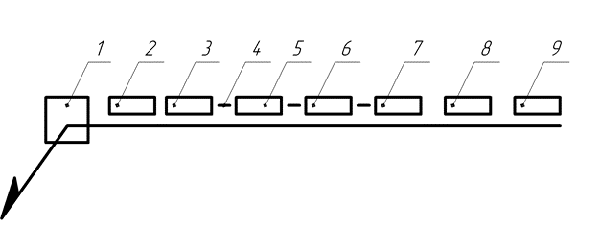
The designation of the welded joint is made on the assembly drawings and general drawings. According to GOST 2.312-72, welds of all types are represented by solid lines (visible seam) or dashed lines (invisible seam). To the images welds call out lines ending in one-way arrows. Leader lines are preferably drawn from the visible seam (Fig. 1). The symbol of the seam is applied over the shelf of the leader line (for the seam on the front side), and under the shelf - for the seam made on the reverse or invisible side.
Fig. 1. Structure of the symbol of the weld
1. Auxiliary signs:

2. Designation of the standard for types and structural elements of seams welded joints:
GOST 5264-80 - standard for welds and joints made by manual arc welding with coated electrodes;
GOST 11534-75 - standard for welds and joints made by manual arc welding of coated electrodes at sharp and obtuse angles;
GOST 14771-76 - standard for welds and joints made by welding in a protective gas environment;
GOST 23518-79 - the standard for welds and joints made by welding in a protective gas environment at sharp and obtuse angles;
GOST 16037-80 - standard for welded joints of steel pipelines (main types, structural elements and sizes);
GOST 14806-80 - standard for the arc welding of aluminum and its alloys with a thickness of 0.8 to 60 mm;
GOST 14776-79 - the standard for welded electro-riveted joints made by welding in a protective gas environment and under a flux layer.
The list of standards used in joining metals by welding is large, and the use of a specific standard is determined based on the welding method used. Joints made by gas welding do not have a special standard. However, the standard GOST 16037-80 regulates the use of gas welding on steel pipelines.
3. Alphanumeric designation of the weld according to the standard for types and structural elements of welded joints.
Possible letters are affixed to the first letter of the type of connection: C, T, H, U. After the letter, a number must be affixed (the serial number of the seam in the standard) indicating the structural elements for preparing the welded edges and the specific conditions for making the welded joint. So, for example, C1 ... C37, etc. There are only two types of lap joints: H1 - the joint is welded on one side indicated in the drawing, H2 - the lap joint is welded on two sides. The amount of overlap of elements is regulated by the standard.
4. The symbol of the welding method according to the standard for types and structural elements of welds of welded joints.
It is allowed not to put down this position when it is clear from the standard what kind of welding method is used. GOST 5264-80 - the standard for welds and joints made by manual arc welding with coated electrodes does not require additional designation. GOST 14771-76 does not disclose a specific welding method, because welding in a shielding gas medium includes several methods: IN - in an inert gas with a non-consumable electrode, INP - in an inert gas with a non-consumable electrode using filler material, UP - in a consumable electrode in a carbon dioxide environment, IP - in a consumable electrode in an inert gas. Therefore, in this case, it is necessary to put down the designation of the welding method. Standards requiring additions to the welding method: GOST 8713-79 (as amended in 1993), GOST 14776-79, GOST 16037-80 (as amended in 1991), etc.
5. For fillet welds in this position, the leg of the seam is inserted, for example, 14 mm.
6. For intermittent seams, the length of the section to be welded is affixed, for electroslap and point joints, the calculated diameter of the weld point is affixed, for seams made by roller welding, the width of the weld, mm
7. The type of intermittency of the joint and the pitch of the joints are indicated: / - joint with a chain arrangement of joints; Z - connection with a staggered arrangement of welds. It is worth paying attention to the values \u200b\u200bof the step size. A step is the distance from the beginning of the seam to the beginning of the next seam, and not the distance between the areas to be welded (this meaning is often put into this size), that is, the designation 100/100 can never be put down. It is also worth considering the appropriateness of the following designation 150 / 160. When making a weld, it will be much more convenient and faster to weld the seam into the aisle (from the beginning to the end of the joint) than to mark it to make intermittent seams. Similarly, when making a welded joint with a staggered arrangement of seams, one should consider the need to make a connection with the specified parameters 150 Z 130.
8. Show auxiliary signs:
- process influxes and roughnesses of the seam with a smooth transition to the base metal;
- a seam along an open line (the sign is used if the location of the seam is clear from the drawing).
9. Show auxiliary signs related to the back of the weld (from the root):
- remove the weld reinforcement;
- the purity of the surface treatment of the weld;
- process influxes and roughnesses of the seam with a smooth transition to the base metal.
If the indicated signs are under the leader line, then they relate to the back of the seam.
There are cases when the weld is visible, but it must be done from the invisible side, while the main inscription of the designation of the weld is written under the leader line (Fig. 2).
For a more convenient reading of the drawing, a number of simplifications are used in the designation of welds and joints.
Applying one method of welding and the form of preparation of edges according to one standard in the manufacture of a welded structure, it is allowed not to put a standard on the main types, structural elements and dimensions of the joints in the structure of the symbol. In this case, the welding standard is indicated on the drawing in the technical requirements for the manufacture of this design. For example, welding is carried out in accordance with GOST 5264-80 with electrodes of the type E-50A.
There may be a situation where there are a lot of identical welds and the designation of each weld clutters the drawing. Then the welds group and produce a complete designation of one weld. On the inclined line of the shelf, the number of identical seams and the number of the group of seams are indicated (Fig. 3, a). The remaining seams draw leader lines (Fig. 3, b).
Fig. 2. Designation of the weld, performed from the invisible side
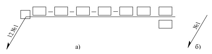
Fig. 3. Designation of identical seams:
a - designation of one seam, b - designation of subsequent seams
They put the serial number of the seam. If the standard for welding is changed in the following welded joints, another edge cutting, etc. is used, then the next group of welded joints is formed. The sequence number of the group does not indicate the sequence of welding or assembly of elements of the welded structure. This sequence can only be found in the technological documentation.
If all seams are the same and are shown on one side (front or back), the serial number of the seams is not assigned, and seams that do not have a designation are marked with leader lines.
A non-standard weld is depicted indicating the dimensions of the structural elements necessary for its implementation, moreover, the seam boundaries are drawn in solid lines, and the structural elements of the edges in the seam boundaries are drawn in solid thin lines (Fig. 4). The technical requirements must indicate the method of welding. For example, manual arc welding with coated electrodes of type E-46A.

Fig. 4. Designation of non-standard weld
The requirements for the discontinuity of the welded joint can be written in its designation in the drawing. allows you to write auxiliary signs in the designation: “Seam is intermittent or spot with a chain arrangement” (hereinafter “Seam with chain arrangement”) or “Seam is intermittent or dot with a checkerboard arrangement” (hereinafter “Seam with a checkerboard arrangement”) (Figure 1).
| Picture 1 |
- designations of a standard weld joint (Figure 2);
- designations of a non-standard weld joint (Figure 3).
Intermittent seam
For intermittent seam Auxiliary signs “Seam with a chain arrangement” and “Seam with a checkerboard arrangement” allow to determine the length of the welded section and the step size.
Figure 4 schematically shows a one-sided weld with a chain arrangement and an indication of the length and pitch of the weld.
An example of a standard weld designation: "GOST 5264-80-T1-50 / 100", where length \u003d 50, step \u003d 100.
Figure 5 schematically shows a double-sided weld with a chain arrangement and an indication of the length and pitch of the weld.
An example of a standard weld designation: "GOST 5264-80-T3-40 / 120", where length \u003d 40, pitch \u003d 120.
Figure 6 schematically shows a double-sided weld with a checkerboard pattern and an indication of the length and pitch of the weld.
An example of a standard weld designation: "GOST 5264-80-T3-50Z100", where length \u003d 50, step \u003d 100.
A checkerboard pattern can only be at a bilateral seam.
For any intermittent seam, the length is always less than a step.
contact welding
The following designations are accepted for structural elements (Figures 7, 8):
t is the distance between the centers of neighboring points in a row (step),
c is the distance between the axes of adjacent rows of points in a chain arrangement,
c1 - the distance between the axes of adjacent rows of points with a staggered arrangement,
u is the distance from the center of the point or axis of the seam to the edge of the lap.
For contact spot welding, the designation of the weld joint includes: the diameter of the cast core of the weld point and the step between the centers of adjacent points in a row. The remaining parameters of the welded joint are selected in accordance with GOST 15878-79 Resistance welding. Welded joints.
Figure 7 schematically shows the seam of contact spot welding with a chain arrangement of points.
An example of a standard weld designation: "GOST 15878-79-Kt-5/20", where the diameter of the weld point \u003d 5, step \u003d 20.
Welded structures are often used in the construction industry, since this method of connection is the most popular. During the design, loads are calculated that both the entire structure and its individual part can withstand. Each method has its advantages and disadvantages, therefore, during the preparation of the project, they consider which of them is most suitable for a particular case. If the choice falls on welding, then it is also determined which of its types will be the most suitable. In the finished project, the drawing contains all the designations necessary for the welder so that he can make the correct version of the metal structure. Therefore, specialists calculate everything regarding the spatial position, the number of sides of the joint and other parameters, therefore. All that remains for the master is to bring everything to life.

For this there is a notation welds in the drawings, each of which carries detailed information regarding the fulfillment of predetermined mounting points on metal structures. Specialists must understand all their features in order to correctly perform the tasks. The success of product construction depends on this, especially when it comes to complex designs. Is indicated here spatial position, seam type and other features. Thus, any master will be able to make a precisely planned design, guided by what designation of the welded joint in the drawing is.
GOST
The main GOST for designations is 2317-72 - Conditional images and designations of welds. In addition, there are:
- 21.502-2007 - Rules for the execution of design documentation for the creation of metal structures;
- Designation of welds in the drawings GOST 5264-80 - Manual electric arc weldingas well as welded joints.
- Designation of welds in the drawings GOST 14771-76 - Arc welding in a protective gas environment, as well as welded joints.
Auxiliary signs
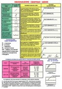
In the drawings, there are often special auxiliary signs that help to abbreviate the required information. There are not so many of them and all of them, together with a decoding of the value, are given below:
| № | Image of auxiliary sign | Symbol designation information | Where should the referenced auxiliary character be located on the leader line | |
| Top line | Bottom line | |||
| 1 | Seam reinforcement required | |||
| 2 | Existing irregularities and sagging must be processed to create a smooth transition from the weld bead to the base metal. | |||
| 3 | The seam must be done during installation of the product, that is, everything is done at the place of use during installation |  |
||
| 4 | Create a point or intermittent seam with a chain seam. The angle should be 60 degrees | |||
| 5 | Create a point or intermittent seam with a checkerboard pattern. | |||
| 6 | Create a seam in a closed line. The diameter of such a sign in the drawing is from 3 to 5 mm. | |||
| 7 | Creates a seam in a non-closed line. This sign is used if the location of the weld is clear from the drawing. | |||
Designation structure
The standard designation of welds has the following structure.
This scheme is found in almost all drawings. Each of its subparagraphs has its own meaning. The designation points for welded joints according to the structure of this scheme are given below:
- 1 - auxiliary characters (from the table above);
- 2 - indicates the standard used;
- 3 – alphanumeric designation used seam according to the above standard, which includes structural elements and types of welded joints;
- 4 - an intermediate sign "hyphen", logically separating the designation;
- 5 - a conditional method for designating the type of welding used to create a joint (A - automatic, W - electroslag, P - mechanized using flux, P-3 - mechanized using fusible electrodes with a protective gas medium).
- 6 - the size and sign of the leg, which corresponds to the selected standard for the types and structural elements of welding.
- 7 - other characteristics of the weld (such as the size of the weld metal roller, the length of the welded section, the size of individual points, the step size and other things).
- 8 - auxiliary signs and surface roughness.
Examples and interpretation of welds in the drawing
The designation of the welds in the drawings may not be completely clear the first time, since they contain a lot of information. In order to understand all the information required to study each of their points. The table shows examples of the main options that occur during welding, as well as their interpretation.
|
Weld Characteristic |
What does a cross-section of a seam look like? |
In accordance with GOST 2.312-72, the seams of welded joints in the drawings indicate solid (visible) and dashed (invisible) lines. The visible single welded point (regardless of the welding method) is conventionally depicted by the “+” sign (see Fig. 1), the invisible single points are not shown. From the image of the seam or a single point, a leader line is drawn with a one-sided arrow and a horizontal line-shelf. The conditional image of the seam is applied on the shelf of the leader line drawn from the image of the seam from the front side (Fig. 1, b), and under the shelf of the leader line drawn from the image of the seam from the back side (Fig. 1, c).
Conditional images of visible and invisible welds:
a - visible electro-rivet, b - visible butt one-sided, c - invisible butt one-sided; 1- joint designation according to GOST
Table number 1.
Auxiliary signs for welds
|
Auxiliary sign |
Auxiliary Sign Meaning |
Location of an auxiliary character relative to a leader line shelf |
||
|
Front side |
On the flip side |
|||
|
Reinforce the seam |
||||
|
Process sag and bumps in the weld with a smooth transition to the base metal |
||||
|
The seam must be made during the installation of the product, i.e., when installed according to the installation drawing at the place of use |
|
|||
|
The seam is intermittent or spot with a chain arrangement. The angle of the line is 60 ° |
||||
|
Intermittent or spot stitch |
||||
|
A seam in a closed line. Sign diameter - 3 ... 5 mm |
||||
|
Open line seam. The sign is applied if the location of the seam is clear from the drawing. |
||||

Notes :
1. 3A, the front side of the unilateral seam of the welded joint accept the one with which the welding is performed.
2. For the front side of the bilateral seam of the welded joint with asymmetrically prepared edges, take the one with which the main seam is welded.
3. For the front side of the bilateral seam of a welded joint with symmetrically prepared edges, either side can be taken.
In fig. 2 shows the structure of the joint symbol. Auxiliary signs for designating welds are given in table. 1, and GOSTs for the main types and structural elements of welded joints - in table. 2. Only auxiliary signs 3 and 6 can be used in the structure of the conditional image of the seam. The designation of the standard can be taken out in technical conditions in the drawing. Manual arc welding letter designation does not have. The welding method can be omitted. Examples of symbols for weld joints are taken from GOST 2.312-72 (Appendix 1) and are presented in table. 3.
If there are identical seams in the drawing, one of the images is marked with the joint number (on the extension line), and leader lines with shelves are drawn from the images of the remaining identical seams, above which are placed the joint number, for example, No. 1 (Fig. . 3). On a leader line with a shelf with a designation, it is allowed to indicate the number of identical seams.

Fig. 2.
Standard joint designation structure
2 - standard designation, 1 - auxiliary signs,
3 - alphanumeric designation of the seam according to the standard for types and structural elements of the weld joints,
4-character "hyphen",
5 - symbol of the welding method (A - automatic, P - mechanized under the flux, P-3 - mechanized by a consumable electrode in shielding gases; W - electroslag, etc.),
6 - the sign and size of the leg according to the standard for types and structural elements of welds,
7 - other characteristics of the seam (length of the welded section, step size, dimensions of individual points, etc.),
8 - auxiliary signs (see table. 1, serial numbers 1, 2, 4, 5 and 7), 9 - surface roughness of the seam.

Fig. 3.
Designation on the drawing of identical seams (the number 12 indicates the number of identical seams)
Table number 2.
GOSTs on the main types and structural elements of welded joints
|
gost |
Welding method |
Connection type |
Joint symbol |
|
|
Manual arc |
Butt |
C ... C27; C39; C40 |
||
|
Tauride |
||||
|
Lap |
||||
|
Tauride |
||||
|
Shielded gas arc |
Butt |
|||
|
Tauride |
||||
|
Lap |
||||
|
The same (at sharp and obtuse angles) |
||||
|
Tauride |
||||
|
Automatic submerged arc |
Butt |
|||
|
Tauride |
||||
|
Lap |
||||
|
The same (at sharp and obtuse angles) |
||||
|
Tauride |
||||
|
Arc of aluminum and aluminum alloys (thickness of elements - 0.8 ... ... 60 mm) |
Butt |
|||
|
Tauride |
||||
|
Lap |
||||
|
Arc and electroslag of two-layer corrosion-resistant steel |
Butt |
|||
|
Tauride |
||||
|
Electroslag |
Butt |
|||
|
Tauride |
||||
|
Arc rivets submerged arc, in carbon dioxide and argon |
Lap |
|||
Table number 3
Examples of symbols for standard seams
|
Cross sectional shape |
The symbol of the seam shown in the drawing |
|
|
on the front side |
on the back side |
|
|
|
|
|
|
The seam butt joint with a curved bevel of one edge, two-sided, performed by manual arc welding during installation of the product. The gain is removed on both sides. The roughness of the weld surfaces from the front side 5, from the reverse 20. |
||
|
|
|
|
|
Angular seam, connection without beveling, two-sided, performed by automatic submerged arc welding with manual welding in a closed line |
||
 |
|
|
|
One-sided lap joint seam without beveling, performed by mechanized arc welding in protective gases by a consumable electrode. Seam - in an open line; leg of the seam - 5 mm |
||


Technical documentation is a kind of book for designers, designers, engineers, craftsmen and workers. It is compiled (written) according to certain rules and requirements. This is required for a correct understanding of the information presented. One area of \u200b\u200ba technical text is the designation of welds in the drawings.
What is a welded joint
The welding process is a technological operation of the formation of a monolithic joint. The area where the material melts and solidifies the parts to be joined is called a weld.
Views
The welded joint is divided into:
- Butt. The connection is formed on the end surfaces of the parts. It is carried out with edge processing and without it. Marking "C".
- Overlap. The planes of the parts are parallel to each other and partially overlap one another. Marking "H".


The seam is performed:
- Unilateral. Deposition is carried out on one of the sides of the joint (joint).
- Bilateral. Processing takes place on two sides.
The need to designate welding
Any design consists of separate parts (nodes), interconnected in one way or another. One of them is welding. The joint has its own characteristics that affect the performance of the product as a whole.
The designation of welding in the drawing is an explanation of the joining method, the shape of the seam and its geometric parameters, the method of execution and other additional information. A competent engineer will draw additional information:
- about strength - the connection is continuous or intermittent; in addition, thermal stresses are formed in the weld zone;
- about the size and shape of the weld metal;
- joint tightness;
- connection execution time - before or during installation, and more.
Decoding technical abbreviation
The study of the designation of the weld in the drawing can be performed in two ways:
- start with the basics - reading special literature, including GOSTs (analog - learning letters in the ABCs);
- go from the opposite, that is, start by looking at examples of how welding is indicated on the drawings, with a gradual deepening of their knowledge.
Examples
The marking of the welding joint is regulated by ESKD. It includes:
- GOST 2.312-72.
- GOST 5264-80.
- GOST 14771-76.
According to GOST, the welded joint is indicated in the technical documentation by the remote arrow:
The location of the inscription on top of the arrow, below it or on both sides indicates the location of the connection:
- from the front of the part;
- reverse (invisible junction);
- double-sided processing.
The inscription and the arrow indicate the reverse (closed) or front part, respectively.
Example 2
- Performed on the one hand, with a bend of the edge, an open circuit, according to the standards of GOST 5264-80, electric arc welding.
Example 3
- - the connection is made along the solid line in the form of a ring;
- GOST 17771-76 - welding in a cloud of gases;
- T3 - T-joint with the processing of each side; no cutting edges;
- UP - gaseous carbon monoxide, a molten electrode;
- 6 - the size of the leg of the welding joint 6mm;
- Periodic design with a welded solid section of 50mm in a checkerboard pattern (Z), step 100mm.
Marking symbols conditionally draw over (under) the shelf of the remote arrow.