A welding arc is a powerful stable electric discharge in a gaseous medium formed between the electrodes, or between the electrodes and the product. The welding arc is characterized by the release of a large amount of thermal energy and a strong light effect. It is a concentrated source of heat and is used to melt basic and filler materials.
Depending on the medium in which the arc discharge occurs, distinguish:
open arc burning in the airwhere the composition of the gaseous medium of the arc zone is air mixed with vapors of the welded metal, electrode material and electrode coatings;
closed arc submerged arcwhere the composition of the gaseous medium of the arc zone is a pair of base metal, wire and protective flux;
shielding arc (the atmosphere of the shielding gas, the vapor of the wire and the base metal are part of the gaseous medium of the arc zone). The welding arc is classified by the type of current used (direct, alternating, three-phase) and by the duration of combustion (stationary, pulsed). When using direct current, an arc of direct and reverse polarity is distinguished. With direct polarity, the negative pole of the power circuit - the cathode - is on the electrode, and the positive pole - the anode - on the base metal. With reverse polarity, plus on the electrode, and minus on the product.
Depending on the type of electrode used, the arc can be excited between the melting (metal) and non-consumable (carbon, tungsten, etc.) electrodes. According to the principle of operation of the arc, there are direct, indirect and combined actions (Fig. 14).

Straight arc called the arc discharge that occurs between the electrode and the product. Indirect arc represents an arc discharge between two electrodes (atomic-hydrogen welding). Combined Arc is a combination of an arc of direct and indirect action. An example of a combined arc is a three-phase arc, in which two arcs electrically connect the electrodes to the product, and the third burns between two electrodes isolated from each other.
Arc excitation is produced in two ways: by touching, or by striking, the essence of which is shown in Fig. fifteen.

In the welding arc, the arc gap is divided into three main areas: the anode, cathode and arc column. In the process of arc burning, there are active spots on the electrode and the base metal, which are more heated sections of the electrode and the base metal through which the entire arc current passes. The active spot located on the cathode is called cathodic, and the spot located on the anode is anode.

The total length of the welding arc (Fig. 16) is equal to the sum of the lengths of all three areas:
L d \u003d L to + L c + L and,
where L d is the total length of the welding arc, cm;
L k is the length of the cathode region, equal to about 10 -5 cm;
L C is the length of the arc column, cm;
L d - the length of the anode region, equal to about 10 -3 ÷ 10 -4 cm.
The total voltage of the welding arc is the sum of the voltage drops in individual areas of the arc:
U d \u003d U to + U c + U and,
where U d is the total voltage drop across the arc, at;
U k is the voltage drop in the cathode region, at;
U c is the voltage drop in the arc column, at;
U a is the voltage drop in the anode region, at.
The temperature in the column of the welding arc ranges from 5,000 to 12,000 ° K and depends on the composition of the gaseous medium of the arc, the material, the diameter of the electrode and the current density. The temperature can be approximately determined by the formula proposed by the academician of the Academy of Sciences of the Ukrainian SSR K.K. Khrenov:
T st \u003d 810 U ef
where T st - the temperature of the arc column, ° K;
U ef is the effective ionization potential.
Static current-voltage characteristic of the welding arc. The dependence of the voltage in the welding arc on its length and the magnitude of the welding current, called the current-voltage characteristic of the welding arc, can be described by the equation
U d + a + bL d
where and is the sum of the voltage drops at the cathode and anode ( and = U to + U and):
b - specific voltage drop in the gas column, referred to 1 mm arc length (value b depends on gas composition arc column);
L d is the length of the arc, mm.
At small and ultrahigh currents U d depends on the magnitude of the welding current.
The static current-voltage characteristic of the welding arc is shown in Fig. 17. In the area I increase in current to 80 and leads to a sharp drop in arc voltage, which is due to the fact that with low-power arcs, an increase in current causes an increase in the cross-sectional area of \u200b\u200bthe arc column, as well as its electrical conductivity. The shape of the static characteristics of the welding arc in this section is falling. A welding arc having a falling current-voltage characteristic has low stability. In the region of II (80 - 800 and) the arc voltage remains almost unchanged, which is explained by an increase in the cross section of the arc column and active spots proportionally to the change in the value of the welding current, therefore, the current density and voltage drop in all sections of the arc discharge are kept constant. In this case, the static characteristic of the welding arc is stiff. Such an arc is widely used in welding technology. With an increase in welding current of more than 800 and (region III) The arc voltage rises again. This is explained by an increase in current density without an increase in the cathode spot, since the electrode surface is already insufficient to accommodate a cathode spot with a normal current density. An arc with an increasing characteristic is widely used in submerged arc welding and in shielding gases.

The processes occurring at the moment of excitation of the welding arc. In the event of a short circuit, the end of the electrode comes into contact with the product. Since the end face of the electrode has an uneven surface, contact does not occur along the entire plane of the end of the electrode (Fig. 18). At the contact points, the current density reaches a very large magnitude and under the action of the released heat at these points the metal instantly melts. At the time of removal of the electrode from the product, the molten metal zone - the liquid bridge is stretched, the cross section decreases, and the metal temperature increases. When the electrode is removed from the product, the liquid metal bridge breaks, rapid evaporation occurs (metal “explosion”). At this moment, the discharge gap is filled with heated ionized particles of metal vapor, electrode coating and air - a welding arc arises. The process of arcing lasts only a fraction of a second. Ionization of gases in the arc gap at the initial moment occurs as a result of thermionic emission from the cathode surface, due to structural disruption as a result of sharp overheating and melting of the metal and electrode coating.

An increase in the electron flux density also occurs due to oxides and formed surface layers of molten fluxes or electrode coatings, which reduce the electron work function. At the moment of breaking of the bridge of liquid metal, the potential drops sharply, which contributes to the formation of field emission. A potential drop allows one to increase the emission current density, accumulate kinetic energy for electrons for inelastic collisions with metal atoms and transfer them to the ionized state, thereby increasing the number of electrons and, consequently, the conductivity of the arc gap. As a result, the current increases and the voltage drops. This occurs to a certain limit, and then a stable state of the arc discharge begins - the burning of the arc.
Cathode region. The processes taking place in the field of cathodic voltage drop play an important role in welding processes. The cathodic voltage drop region is a source of primary electrons that support the gases of the arc gap in an excited ionized state and transfer the bulk of the charge on them due to their high mobility. The separation of electrons from the cathode surface is caused primarily by thermionic and field emission. The energy spent on the removal of electrons from the cathode surface and the deposition of the metal is to some extent offset by energy from the arc column due to the flow of positively charged ions that give their ionization energy on the cathode surface. The processes occurring in the region of the cathodic voltage drop can be represented as follows.
1. Electrons, emitted from the surface of the cathode, receive the accelerations necessary for the ionization of molecules and gas atoms. In some cases, the cathodic voltage drop is equal to the gas ionization potential. The magnitude of the cathodic voltage drop depends on the ionization potential of the gas and can be 10 - 16 at.
2. Due to the small thickness of the cathode zone (about 10 -5 cm) the electrons and ions in it move without collisions and it is approximately equal to the mean free path of the electron. The values \u200b\u200bof the thickness of the cathode zone, found empirically, less than 10 -4 cm.
3. With increasing current density, the temperature of the cathode region rises.
Pillar of the arc. In the arc column there are three kinds of charged particles - electrons, positive ions and negative ions, which move to the opposite sign in the pole.
The arc column can be considered neutral, since the sum of the charges of negative particles is equal to the sum of the charges of positive particles. The arc column is characterized by the formation of charged particles and the reunion of charged particles into neutral atoms (recombination). The flow of electrons through the gas layer of the discharge gap causes mainly elastic collisions with the molecules and atoms of the gas, resulting in a very high temperature. Ionization due to inelastic collisions is also possible.
The temperature of the arc column depends on the composition of the gases, the magnitude of the welding current (the temperature rises with increasing magnitude of the current), the type of electrode coatings and polarity. With reverse polarity, the temperature of the arc column is higher.
Anode region. The anode region has a greater length and a smaller voltage gradient than the cathode region. The voltage drop in the anode region is created as a result of the extraction of electrons from the column of the arc discharge and acceleration when they enter the anode. In the anode region there is mainly only an electronic current, due to the small number of negatively charged ions having lower speeds than the electron. An electron that has fallen on the anode surface gives the metal not only a supply of kinetic energy, but also energy of the work function, therefore the anode receives energy from the arc column not only in the form of electron flow, but also in the form of thermal radiation. As a result, the temperature of the anode is always higher and more heat is released on it.
Features of the welding arc powered by alternating current. When welding with an alternating current arc (industrial frequency of 50 periods per second), the cathode and anode spots change places 100 times per second. When the polarity changes, the so-called “valve effect” is formed, which consists in partial rectification of the current. The rectification of the current occurs as a result of continuously changing electron emission, since when the current direction changes, the conditions for the output of the emission currents from the electrode and from the product will not be the same.
With the same materials, the current is almost not rectified, the rectification of the current in the welding arc is called dC componentwhich at argon arc welding aluminum negatively affects the process. The burning stability of a welding arc powered by alternating current is lower than that of an arc fed by direct current. This is due to the fact that during the transition of the current through zero and polarity changes at the beginning and end of each half-cycle, the arc fades. At the time of extinction of the arc, the temperature of the arc gap decreases, causing deionization of the gases of the arc column. At the same time, the temperature of active spots decreases. The temperature drops especially on the active spot, which is located on the surface of the weld pool, due to heat removal to the product. Due to the thermal inertia of the process, the temperature drop somewhat lags behind the phase transition of the current through zero. Arc ignition due to reduced ionization of the arc gap at the beginning of each half-cycle is possible only with increased voltage between the electrode and the product, called the ignition peak. If the cathode spot is on the base metal, then in this case the magnitude of the ignition peak is slightly higher. The magnitude of the ignition peak is affected by the effective ionization potential: the greater the effective ionization potential, the higher the ignition peak should be. If there are easily ionizable elements in the welding arc, the ignition peak decreases and, conversely, it increases when there are fluorine ions in the atmosphere of the arc, which, when combined with positive ions, easily form neutral molecules.
The main advantages of an alternating current arc include: relative simplicity and lower cost of equipment, the absence of magnetic blasting and the presence of cathodic sputtering of an oxide film during argon-arc welding of aluminum. Cathodic sputtering is the process of bombarding the weld pool with positive ions at the moment when the product is a cathode, due to which the oxide film is destroyed.
The effect of magnetic field and ferromagnetic masses on the welding arc
In a welding arc, the arc column can be considered as a flexible conductor through which an electric current passes and which, under the influence of an electromagnetic field, can change its shape. If conditions are created for the interaction of the electromagnetic field arising around the welding arc, with extraneous magnetic fields, with the own field of the welding circuit, as well as with ferromagnetic materials, then in this case there is a deviation of the arc discharge from the original own axis. In this case, the welding process itself is sometimes disrupted. This phenomenon is called magnetic blast.
Consider a few examples showing the effect of an external magnetic field on a welding arc.
1. If a symmetric magnetic field is created around the arc, then the arc does not deviate, since the created field has a symmetrical effect on the arc column (Fig. 19, a).
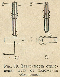
2. An asymmetric magnetic field acts on the pole of the welding arc, which is created by the current flowing in the product; the arc column will deviate in the direction opposite to the current lead (Fig. 19.6).
The angle of inclination of the electrode, which also causes arc deflection, is also significant (Fig. 20).

A strong factor affecting arc deflection is ferromagnetic masses: massive welded products (ferromagnetic masses) have a greater magnetic permeability than air, and magnetic field lines always tend to pass through a medium that has less resistance, therefore, an arc discharge located closer to ferromagnetic mass, always deviates in its direction (Fig. 21).

The influence of magnetic fields and ferromagnetic masses can be eliminated by changing the location of the current supply, the angle of the electrode, by temporarily placing the ferromagnetic material to create a symmetrical field and replacing the direct current with a variable.
Transfer of molten metal through an arc space
During the transfer of molten metal, gravity, surface tension, electromagnetic field and internal gas pressure act.
Gravity is manifested in the tendency of the droplet to move down due to its own weight. When welding in the lower position, gravity plays a positive role in transferring the droplet to the weld pool; when welding in vertical and especially in ceiling positions, it complicates the process of transfer of electrode metal.
Surface tension It manifests itself in the tendency of a liquid to reduce its surface under the influence of molecular forces that tend to give it such a form that would have a minimum energy reserve. This form is a sphere. Therefore, the surface tension force gives the drop of molten metal a ball shape and retains this shape until it touches the surface of the molten bath or the drop comes off the electrode end without contact, after which the surface tension of the bath metal “draws” the drop into the bath. The force of surface tension helps to keep the molten metal of the bath during welding in the ceiling position and creates favorable conditions for the formation of the seam.
The strength of the electromagnetic field lies in the fact that the electric current passing through the electrode forms a magnetic force field around it, which exerts a compressive effect on the surface of the electrode, which tends to reduce the cross section of the electrode. The magnetic force field does not affect a solid metal. Magnetic forces acting normally to the surface of a molten drop having a spherical shape have a significant effect on it. With an increase in the amount of molten metal at the end of the electrode under the influence of surface tension forces, as well as compressive magnetic forces, an isthmus forms between the molten and solid electrode metal (Fig. 22).

As the isthmus cross section decreases, the current density sharply increases and the compressive action of magnetic forces increases, tending to tear the drop from the electrode. Magnetic forces have a minimal compressive effect on the spherical surface of the droplet facing the molten bath. This is because the current density in this part of the arc and on the product is small, so the compressive effect of the magnetic force field is also small. As a result, the metal is always transferred in the direction from the electrode of small cross-section (rod) to the electrode of large cross-section (product). It should be noted that in the resulting isthmus, due to the increase in resistance during the passage of current, a large amount of heat is generated, leading to strong heating and boiling of the isthmus. The metal vapors formed during this overheating at the moment of droplet detachment exert a reactive effect on it — they accelerate its transition to the bath. Electromagnetic forces promote metal transfer in all spatial provisions welding.
The force of the internal gas pressure arises as a result of chemical reactions that proceed the more actively, the more the molten metal at the end of the electrode is overheated. The initial products for the formation of reactions are gases, and the volume of gases formed is ten times greater than the volume of the compounds involved in the reaction. The separation of large and small drops from the end of the electrode occurs as a result of rapid boiling and removal of the formed gases from the molten metal. The formation of splashes on the base metal is also explained by the explosive fragmentation of the droplet when the droplet passes through the arc gap, since at this moment the emission of gases from it increases, and some of the droplet flies out of the weld pool. The force of the internal pressure of the gases mainly moves the droplet from the electrode to the product.
Main indicators of a welding arch
Fusion coefficient. When welding metal, the seam is formed due to the melting of the filler and the penetration of the base metal.
The melting of the filler metal is characterized by a melting coefficient
where α p is the melting coefficient;
G p is the weight of the molten over time t electrode metal g
t - arc burning time, h;
I - welding current and.
A welding arc is a powerful, long-lasting electric discharge between energized electrodes in a mixture of gases and vapors. The arc is characterized by high temperature and high current density. The welding arc as a consumer of energy and the power source of the arc (welding transformer, generator or rectifier) \u200b\u200bforms a mutually connected energy system.
There are two modes of operation of this system: 1) static, when the voltage and current in the system do not change for a sufficiently long time; 2) transitional (dynamic), when the voltage and current in the system are continuously changing. However, in all cases, the combustion mode of the welding arc is determined by the current (I D), voltage (U D), the gap between the electrodes (the so-called arc gap) and the connection between them.
Three areas are distinguished in the arc gap I D (Fig. 1a): anodic 1, cathodic 2 and column of arc 3. The voltage drop in the anodic and cathodic regions is constant for these welding conditions. The voltage drop per unit length of the arc column is also a constant value. Therefore, the dependence of the arc voltage on its length is linear (Fig. 1, b).
The stability of the welding arc is determined by the ratio between current and voltage. A graphical representation of this dependence (Fig. 2) with a constant arc length is called the static current – \u200b\u200bvoltage characteristic of the arc. Three main sections are clearly visible on the graph: increase in current in the section I accompanied by a decrease in voltage on the arc; Location on II arc voltage varies little; Location on III tension rises. The combustion modes of the welding arc corresponding to the first section are unstable at the voltages of existing power sources. In practice, the welding arc will be stable in the second and third sections of the current-voltage characteristic. With an increase or decrease in the length of the arc, the characteristics shift to positions 2 and 3, respectively (see Fig. 2). For electrodes of a smaller diameter, the characteristics are shifted to the left, of a larger diameter - to the right.

Fig. 1. Welding arc burning between non-consumable electrodes: a - arc diagram, b - dependence of the arc voltage (Ud) on the size of the arc gap (/ d): 1 - anode region, 2 - cathode region, 3 - arc column

Fig. 2 Volt-ampere characteristic of the arc (CVC)
Shown in fig. 2 volt-ampere characteristic of the arc is taken at a constant length of the welding arc. When welding with a consumable electrode, the length of the arc gap continuously changes. In these cases, you should use the characteristics that determine the relationship between voltage and arc current at a constant feed rate of the electrode wire (Fig. 3, curves 1 and 2). Each feed rate corresponds to a certain range of currents at which the welding arc stays steady and the electrode melts. In this case, with small changes in current, the voltage varies over large limits. This dependence is called the characteristic of sustainable operation. It, like the current-voltage characteristic, depends on the length of the electrode and the feed rate.
These regularities are valid for direct and alternating current, since the nature of the current does not affect the shape of the current – \u200b\u200bvoltage characteristics of the electric arc. The shape of the characteristic is affected by the geometry and material of the electrodes, the cooling conditions of the arc column, and the nature of the medium in which the discharge occurs.
The stability of the welding arc and the welding mode depend on the conditions of the existence of the arc discharge and the properties, parameters of the power sources and the electric circuit. The external characteristic of the power source (curve 3 in Fig. 3) is the dependence of the voltage at its terminals on the load current. The following external characteristics of power sources are distinguished (Fig. 4): falling 1, gently falling 6, hard 5, increasing 3 and vertical 2. A power source with one or another external characteristic is selected depending on the welding method. The adjusting device of each source gives a number of external characteristics (“family of characteristics”). The established mode of operation of the system: “welding arc - power source” is determined by the point of intersection A of the external characteristic of the power source (1, 2, 3, 5 or 6) and the current-voltage characteristic 7 of the welding arc.

Fig. 3 Volt-ampere characteristic of the welding arc (CVC) 1.2 at a constant wire feed speed (characteristic of stable operation) and external characteristics of power supplies 3, 4 and 5

Fig. 4 External characteristics of power supplies 1, 2, 3, 5, 6 and current-voltage characteristics of the welding arc 4, 7
The welding process will be stable if for a long time an arc discharge exists continuously at specified voltage and current values. As can be seen from fig. 4, at points A and B of the intersection of the external characteristics of the arc 7 and the power source, there will be an equilibrium in current and voltage. If for any reason the current in the welding arc corresponding to point A decreases, its voltage will be less than the steady-state value of the voltage of the power source; this will lead to an increase in current, that is, to a return to point A. On the contrary, with a random increase in current, the steady-state voltage of the power source is less than the arc voltage; this will lead to a decrease in current and, consequently, to the restoration of the combustion mode of the welding arc. From similar reasoning, it is clear that at point B, the welding arc burns unstably. Any random changes in the current develop until it reaches a value corresponding to the point of stable equilibrium A or until the arc breaks. With a dipping external characteristic (curve 6), stable arc burning will also occur at point A.
When working on a falling section of the current-voltage characteristics of the arc, the external characteristic of the source at the operating point should be more steeply falling than the static characteristic of the welding arc. With increasing characteristics of the arc, the external characteristics of the source can be rigid 5 or even increasing 3.
In manual welding, when changes in the length of the arc are possible, it should have a sufficient margin of stability.
Other things being equal, the stability margin increases with the steepness of the external characteristics of the power source. Therefore, sources with steeply falling characteristics are used for manual welding: a welder can lengthen the arc without fear that it will break, or shorten it without fear of excessive current increase.
Welding arc self-regulation. When automatic or semi-automatic welding a melting electrode, its feed rate (va) is equal to the melting rate. With an accidental decrease in the arc gap (curve 4 in Fig. 4), the current increases and the wire begins to melt faster. As a result, the arc gap will gradually increase and the welding arc will reach its original length. The same will happen if the arc is lengthened accidentally. This phenomenon is called self-regulation of the welding arc, since the restoration of the initial mode occurs without the influence of any regulator. Self-regulation occurs the more actively, the better the external characteristic of the power source and the greater the feed rate of the electrode. Therefore, for mechanized welding with a consumable electrode, power sources with damping external characteristics should be selected. When welding with direct current in shielding gases, when the static characteristic of the welding arc takes on an increasing form, it is rational to use sources with a rigid characteristic for self-regulation systems. However, their open circuit voltage is small and may even be less than the operating voltage of the arc, which complicates its initial excitation. In these cases, the use of power sources is desirable, in which the external characteristic in the working part is rigid or gently increasing the current-voltage characteristic, and the open circuit voltage is slightly increased, as shown by the dotted line in Fig. 4.
The AC welding arc requires reliable re-excitation of the welding arc from the power sources. This is achieved by the correct choice of the relationship between open circuit voltage, ignition and arc burning and welding circuit parameters. The easiest way to obtain a stable welding arc is to include reactance in the welding circuit. Due to this, at the moment of re-excitation of the arc, the voltage on the arc can increase sharply (Fig. 5) to the value of the ignition voltage (U3). The dashed t / xx curve shows the voltage of the power source at idle. Under load, due to the presence of reactance, the welding current lags behind the voltage in time.
When the arc breaks, the voltage across the arc gap should rise to a value corresponding to the instantaneous value of the open circuit voltage of the power source. Due to the lag of the current from the voltage, this voltage is sufficient to re-excite the welding arc (Un).
Metal transfer in the welding arc and requirements for the dynamic properties of power sources. The following types of electrode metal transfer to the weld pool are distinguished: large-droplet, characteristic for low current densities; small droplet, jet, when the metal flows from the electrode in very small drops. Drops of molten metal periodically close the arc gap, or if short circuits do not occur, periodically change the length of the arc. At a high current density, small droplet metal transfer is observed in the electrode, without noticeable fluctuations in the length and voltage of the welding arc.
Voltage, current and arc length undergo periodic changes from idle to short circuit; in the operating mode, the arc burns, the formation and growth of the drop. Subsequently, with a short circuit between the drop and the bath, the current increases sharply. This leads to compression of the droplet and to the destruction of the bridge between the droplet and the electrode. The voltage rises almost instantly and the welding arc is excited again, i.e. the process is periodically repeated. Change of modes occurs within a split second. Therefore, the power source must have high dynamic properties, i.e., a high rate of voltage increase when the circuit breaks and the desired current rise rate.

Fig. 5 Oscillogram of current and arc voltage during AC welding.
At a low rate of current rise, an unmelted wire enters the bath. It is relatively slowly heated in a large area, which then collapses. If the current rises too quickly, the bridge between the bath and a drop of electrode metal quickly overheats and collapses with an explosion. Part of the molten metal is sprayed and does not fall into the seam.
To avoid splashing, it is necessary to increase the electromagnetic inertia of the power source by increasing the inductance of the welding circuit.
What is the principle of arc welding? From the welding transformer, electric current is supplied to the electrode and the welded product, which creates and maintains an electric arc. The electric arc is heated to 7000 degrees, so that the electrode and the edges of the welded products melt and form the so-called weld pool. The weld pool is in a molten state for a short time. At this time, the molten metal of the electrode is mixed with the molten metal of the article, and a protective film is formed. After the weld pool has solidified, a welded joint is formed.
The electrical energy that is needed to create and maintain an electric arc is generated in AC or DC sources.
Volt-ampere characteristic of the arc.
The current-voltage (static) characteristic of the arc is the dependence of the arc voltage on the current of the external network.
The arc voltage during welding directly depends on the magnitude of the welding current and the length of the arc itself. In manual arc welding, the lower the voltage, the lower the voltage on the arc. In an automatic welding process, the arc voltage depends only on the length of the arc itself: the longer the electric arc, the higher its voltage, resulting in an increase in the amount of heat used to melt the metal and flux.
The arc voltage increases to the maximum value, after which it remains unchanged until the electric arc goes out.
Arc voltage affects the final result of welding - the quality of the seam and the thickness of the weld. The higher the voltage, the wider the seam and the lower the penetration depth of the product. Changing the arc voltage can lead to the appearance of so-called pores and drops of molten metal.
The arc voltage during manual welding varies within a small range - 15-30 Volts, however, at the time of replacing the electrode, the voltage can increase to 70 Volts.

The dependence of the arc voltage on the voltage in automatic welding.
As the voltage increases to 80 V, the voltage on the arc decreases sharply during welding (region I, Fig. 2). With a small arc power, with increasing current, the cross-sectional area and the ability of the arc column to conduct electricity expand. This static characteristic of an arc is called falling; the falling arc has low stability. With increasing voltage from 80 to 800 V (region II, Fig. 2), the arc voltage is almost unchanged. This is primarily due to the fact that the cross section of the arc column and active spot increases. This increase occurs in proportion to the change in the value of the welding current, which is why the current density, and therefore the arc voltage, does not change. This static characteristic of an arc is called tough. A rigid arc is most often used in welding equipment. With an increase in the voltage of more than 800 V, the voltage of the arc itself again increases (region III, Fig. 2). The growth of the cathode spot does not increase with increasing voltage, due to which the current density increases, and with it the arc voltage. Such an arc, called increasingactively used in welding workah submerged and in shielding gases and gas mixtures.
The arc voltage depends on either the voltage or the arc length, depending on the type of welding work - automatic or manual. Regarding manual welding, I would like to note that during electrode replacement, the arc voltage rises to 70 V, so the welder should be extremely careful. In an automatic welding process, the probability of electric shock is much lower.
Physical fundamentals of welding materials
Welding is the process of joining various solid materials at high temperature. Its essence lies in the emergence of atomic-molecular bonds between the structural components of the connecting products. It was designed to combine the metal surfaces of various parts. Therefore, its essence and mechanism will be considered on metallic materials.
The process can be carried out in two ways: melting and pressure.
The first is that the temperature in the area of \u200b\u200bthe connection of the metal surfaces is brought to the corresponding melting points and each of them melts. Then, both liquid metals merge together to form a common weld pool, which crystallizes upon cooling to form a solid layer called a weld.
In the second case, at high pressure, the metal exhibits increased plastic deformation and it begins to flow, like a liquid. Further, everything happens as in the previous case.
Each of the above methods is in turn classified according to the principle of its implementation.
Fusion welding should include soldering characterized in that only the filler material is melted, and the main metal being welded remains unmelted, while the main metal is partially melted during welding.
Dominant position in production metal structures last 70 years takes arc welding. She carries out more than 60% of the total volume of welding work. While there is no other method that can compete with arc welding in its simplicity and versatility.
In 1881, N.N. Benardos discovered arc welding. In 1888 - 1890 Russian engineer N. G. Slavyanov developed and patented arc welding with a metal electrode, which is also a filler material. In 1907, the Swedish engineer O. Kjelberg used coated metal electrodes, which improved the quality of welded joints.
A welding arc is a powerful electric discharge between electrodes located in the environment of ionized gases and vapors.
By the method of influencing the metal during the welding process, the arc is of indirect (independent) and direct (dependent) action. In the first case, the base metal is not included in the welding circuit and is heated mainly due to heat transfer from the gases of the arc and its radiation. This method is currently not used in industry.
Classification of welding methods
In direct arc welding, metal belongs to the elements of the welding circuit and acts as one of the electrodes. It is heated mainly by bombarding its surface with electrically charged particles. The specific power of heating the metal surface in this case in the region of the electrode spot is very high and ranges from 10 3 to 10 5 W / cm 2.
Welding is carried out by melting and non-consumable electrodes. The first is called welding according to the method of N. G. Slavyanov, and the second - according to the method of N. N. Benardos.
Melting electrodes are made of steel, aluminum and some other metals. They still play the role of filler material, of which the welded metal seam largely consists. Carbon (graphite) or tungsten electrodes are non-consumable and do not participate in the formation of the weld. In this case, the filler material is introduced additionally from the side in the form of a wire or rod.
To power the arc can be applied direct or alternating, single or multiphase currents, low or high frequency; it is possible to use complicated combined schemes.
When welding, the following mode is used: U d \u003d 10 - 50 V; \u003d 1 - 3000 A; R d \u003d 0.01 - 150 kW, where I d is the current strength, U d is the voltage and R d is the arc power.
The ignition of the arc is performed by short-circuiting the electrode to the product. Short-circuit current (short circuit) almost instantly melts the metal at the point of contact, resulting in the formation of a liquid jumper. When the electrode is removed, it stretches, the metal overheats and its temperature reaches the boiling point; metal vapors and gases under the influence of thermo- and field emission are ionized - an arc is excited. When welding with a non-consumable electrode, the arc is excited in an uncontrolled manner, ionizing with high-frequency pulses.
The base of the arc are sharply defined, brightly glowing spots on the surface of the electrodes. All current passes through them, the density of which can reach several hundred amperes per 1 mm 2. In a DC arc, cathode and anode spots are distinguished. The electrically conductive gas channel between the spots is a plasma - a mixture of neutral atoms, electrons and ions from the atmosphere surrounding the arc, and from the substances that make up the electrodes and fluxes. It has the shape of a truncated cone and is divided into 3 areas: cathodic length of the order of 10 -3 - 10 -4 mm, anode - a thickness of 10 -2 - 10 -3 mm and the column of the arc. The arc column is the longest and highest temperature zone. The temperature on its axis reaches 6000 - 8000 K. The temperature of the spots is much lower - it is usually close to the boiling points of the electrode material (for steel - 3013 K). Therefore, a temperature gradient is very large in both regions (about 3 × 10 6 K / mm), which creates a powerful heat flux from the arc column to the cathode and anode spots.
In the arc column, the voltage drop is small; the field strength in it is only 1 - 5 V / mm and is almost independent of length. A significant part of the arc voltage drops in the near-electrode regions; 4 - 5 V in the anode region and from 2 to 20 V in the cathode region. The length of the regions is small; therefore, the field strength in them reaches 2 × 10 5 and 10 3 V / mm, respectively.
The power released in the arc column is determined by the field strength, arc current strength and column length. It is partially spent on heating the metal, to a certain extent - it is scattered by radiation into space. The greater the penetration of the arc into the welded metal, the lower the radiation loss of the column and the higher the efficiency of the arc (COP).
The arc voltage, i.e., the potential difference between the electrodes, depends on the arc length, current strength, as well as on the materials and sizes of the electrodes and the composition of the arc plasma.
The dependence of the arc voltage on the current strength at a constant arc length is called the static current-voltage or simply static characteristic of the arc. It is non-linear and consists of three sections - falling I, hard II and ascending III. For an arc 4 mm long with a melting steel electrode with a diameter of 4 mm, the boundary of the incident section is approximately 40-50 A, and the hard one is approximately 350 A.


Static characteristic of a welding arch:
At low currents (section I in Fig. 13.4, a), the heat fluxes from the near-electrode regions to the electrode spots are insufficient for heating the latter to the boiling points of the electrode material. Therefore, the temperature difference between the arc column and electrode spots is very large, which means that the voltage drop in the electrode regions is also large. Moreover, the decrease in U in the column is also significant, since it is relatively “cold” and the degree of gas ionization is small. Therefore, for burning an arc at low currents, a high voltage is required. With an increase in the current strength, the temperatures of heating of the electrode spots and the arc column increase, which means that the decrease in U in the near-electrode regions and in the arc column decreases. As a result, the arc voltage decreases with increasing amperage, and the characteristic is incident.
A change in the current strength in the region of average values \u200b\u200bis accompanied by a proportional modification of the cross section of the arc column and the areas of both spots (their diameter is less than that of the electrode). The current density in the column does not change, and the arc voltage as a whole remains constant.
In the area of \u200b\u200bhigh currents, the cathode spot covers the entire end of the electrode; the increase in current strength does not occur due to an increase in the area of \u200b\u200bthe conductive channel, but due to the increase in density. Therefore, to increase the current strength, it is necessary to raise the voltage, and the relationship between them is almost linear. The smaller the diameter of the electrode, the lower the current strength at which the characteristic of the arc becomes increasing. With a constant current strength, the arc voltage almost linearly depends on its length:
U d \u003d and + bl,
where and - the sum of the voltage drops in the cathode and anode regions; l - arc length; b - tension (voltage gradient) of the arc column. For steel electrodes and \u003d 8 - 25 V; b \u003d 2.3 - 4.3 V / mm. Therefore, an increase in the length of the arc, ceteris paribus, leads to a shift of its static characteristic up, a decrease to down, since the voltage drop in the arc column varies in proportion to its length (Fig. 13.4, c).
The welding arc can operate on direct and alternating current. The arc is supplied with alternating current from a welding transformer, and constant - from welding rectifiers and generators. Most generators are collector driven by three phases of an induction motor or from an internal combustion engine. A generator complete with a drive from an induction motor is called a welding transducer, and from an internal combustion engine - an assembly. The latter are used mainly for welding in field conditions, where there are no electric networks.
Most sources are designed to supply current to a single welding station. But in workshops with a large number of welding stations, it is more economical to use multi-station sources supplying several stations simultaneously.
Direct current has certain technological advantages over alternating current. On it the arc burns more steadily. By changing its polarity, you can adjust the ratio between the intensity of heating of the electrode and the product. Therefore, for a long time it was believed that high-quality welded joints can only be obtained with direct current. However, modern electrodes make it possible to obtain high-quality seams on alternating current on most materials. Using AC to power the arc has several advantages. The main one is profitability. The efficiency of the welding transformer is about 0.9; rectifier - about 0.7; and a transformer with a collector generator is approximately 0.45.
Thus, AC welding is energetically twice as profitable as working with a converter. In addition, the welding transformer is significantly more reliable, simpler to operate and lighter than DC power supplies. Therefore, most of the volume of arc welding is performed by alternating current.
An external volt-ampere or simply an external characteristic of an arc power source is the relationship between the current and the voltage at its output in steady state. It can be steep and dipping, rigid and upward. Different welding processes require power supplies with a variety of external characteristics.

External characteristics of power supplies:
1, 2 - steep and dipping; 3 - hard; 4 - increasing
For manual arc welding with both a consumable and non-consumable electrode, power supplies with steeply dipping characteristics are required. Typical for manual welding is the variation in arc length. Therefore, in order for the dimensions of the weld pool and the cross-section of the seam to be constant, it is necessary to ensure the constancy of the current with changes in the length of the arc. This is achieved using a power source with steeply dipping characteristic.
When the arc burns, the current and voltage at the output of the power source are equal to the same parameters of the arc. The arc burning mode is determined by the intersection point of the corresponding external and static characteristics. In fig. 13.6, and there are two such points, but the arc will burn steadily only at the steady state corresponding to point B. This is explained as follows. If, for any random reason, the arc current decreases, the source voltage will become greater than U d and cause an increase in I in the circuit, i.e., return to step B. If the arc current increases, then its voltage will be greater than that of the power source, which again leads to point B.
Thus, the equilibrium corresponding to this point in the arc-source system is self-settling. Similar considerations show that the slightest deviation of the arc mode from point A develops either before the arc breaks, or before moving to point B.


External characteristic of the power source (a, c)
and static characteristics of the arc in manual arc welding (b)
Thus, for stable arc burning, it is necessary that the slope of the external characteristic of the source is greater than the slope of the static characteristic of the arc at the point of intersection.Therefore, when operating in the modes corresponding to the falling section of the static characteristic of the arc, the external characteristic of the source should be even more steep. When operating in modes corresponding to the almost horizontal portion of the static characteristic of the arc, it will stably burn with steeply dipping and with a dipping characteristic of the source. If the arc mode corresponds to the ascending section of the static characteristic, then the burning stability of the arc is ensured for any characteristic - steeply dipping, sloping, rigid and ascending. In practice, additional restrictions on the type of characteristic are imposed by the device of the wire electrode feeding mechanism for mechanized welding. Depending on it, power sources with rigid or sloping characteristics are used.
With changes in the length of the arc, its static characteristic shifts up or down and accordingly shifts the point of intersection of the static characteristic of the arc with the external characteristic of the source, i.e., the current mode. But the magnitude of the change in the arc current during manual welding does not exceed several percent, since the characteristic of the power source is steeply dipping.
Arc voltage is determined by the formula (7.1.4):
The feed rate is determined by the floor using the formula (7.1.5), the melting factor of the solid electrode wire is selected within the range of 8 - 12 g / A ∙ h, formula (7.1.6):

56 src \u003d "images / referats / 13263 / image037.png"\u003e
The quality of the restored layer is influenced by the step of deposition, which is determined by the width of the deposited bead and depends on the arc voltage:
![]() (7.2.1)
(7.2.1)
Deposition Speed:
 (7.2.2)
where Kp is the coefficient of transition of the electrode metal into the weld,
a is a coefficient taking into account the deviation of the area of \u200b\u200bthe weld bead from the area of \u200b\u200bthe rectangle, a \u003d 0.7;
The coefficient of transition of the electrode metal into the weld is determined by the formula:
where Ψ is the loss coefficient of the electrode metal, Ψ \u003d 10%;
![]()
![]()
When choosing a deposition rate, it should be borne in mind that between the electrode wire feed speed and the deposition rate, the ratio Vel / Vn equal to 1.5 - 2.5 must be maintained. This requirement is met: Vel / Vn \u003d 86.23 / 58.02 \u003d 1.5.
Amplitude of vibration, mm, end of electrode wire:
Smaller values \u200b\u200bof voltage on the arc correspond to a smaller amplitude of vibration of the electrode wire.
The reach of the electrode is set within 10 - 12 mm.
The inductance of the welding circuit is formed due to the inductance of the power source and the external inductance of the welding circuit. Since the inductance of the rectifiers and generators used is small, an additional inductance is included in the circuit.
As inductive resistance, chokes RSTE-24 L \u003d 0.12 GN can be used.
Surfacing is carried out with direct current of reverse polarity by sources with a rigid external characteristic.
To protect the deposited metal, liquid, carbon dioxide and flux are used. Fluid supplied to the tail of the weld pool. It ionizes the arc burning zone well and provides quick cooling of the part, as a result of which the deformation of the part and the dimensions of the heat-affected zone are minimal, and the hardness and wear resistance of the deposited metal are highest. The disadvantage of using the liquid is the low fatigue strength of the restored part, which is due to the appearance of pores, cracks and structural heterogeneity of the deposited layer.
- an aqueous solution containing 5% soda ash, 1% laundry soap and 0.5% glycerol;
- an aqueous solution containing 20 to 30% glycerol, etc.
When surfacing parts from medium - and high-carbon and alloy steels, the fluid flow rate is 0.3 - 0.5 l / min, for low-carbon - 1 l / min or more. When surfacing thin-walled parts of small diameters, the fluid flow rate can be in the range of 3 - 5 l / min.
After calculating the modes of two automatic surfacing: under the fused flux and vibrating arc, analyzing the obtained values \u200b\u200bof the surfacing speed Vн, we conclude that it is more economical and more efficient to eliminate wear of the surface of the part using surfacing having a high speed in magnitude, i.e. by means of automatic vibratory arc surfacing, at which the calculated value of the velocity Vn is 104.4 m / h.
8. Customized machining
With this repair method, the part as a result of machining receives a new size that differs from the original (nominal) size according to the working drawing, the correct geometric shape and the required surface roughness. This new part size is called repair, and it may be larger or smaller than the nominal.
The machining allowance for the size is selected based on the geometrical dimensions of the part and the amount of wear on the treated surface: δ0 \u003d 0.6 mm
We accept the cutting lip equal to the machining allowance for the size: t \u003d 0.6 mm.
The initial feedrate for rough milling is the feed per tooth Sz \u003d 0.2 mm.
Cutting speed - peripheral cutter speed, m / min,

where Cv is a constant depending on the type of processing, the properties of the tool and processed materials, Cv \u003d 332 mm;
D is the diameter of the cutter, D \u003d 90 mm;
T is the resistance period, T \u003d 180 mm;
Sz - feed per tooth, Sz \u003d 0.2 mm;
B-width of milling, B \u003d D / (1.25 - 1.5) \u003d 90 / 1.25 \u003d 72 mm;
Z is the number of teeth of the cutter, Z \u003d 16;
Kv - general correction factor for cutting speed, taking into account the actual cutting conditions;
exponents:
The total correction factor for cutting speed, taking into account the actual cutting conditions Kv, is determined by the formula:
![]()
where Kmv– coefficient taking into account the quality of the processed material, Kmv \u003d 1;
Kpv– coefficient taking into account the surface condition of the workpiece Kpv \u003d 1;
Kiv– coefficient taking into account the material of the instrument, Kiv \u003d 1.5;
![]()
The cutting frequency is determined by the formula (6.3), rpm:

The surface size control after surfacing and machining is carried out with a ruler or vernier caliper, the obtained value is compared with the nominal value. In case of discrepancy, the part is re-surfaced, followed by machining to size and again controlled.
9. The calculation of technological costs for automatic surfacing submerged arc
At the stage of rationing the technological process, the initial data necessary for calculating the norms of time and material consumption are established; calculate and normalize labor costs, consumption rates of materials necessary for the implementation of the process; determine the category of jobs and professions of performers to perform operations depending on these jobs.
To solve these problems, use the standards of time, consumption and prices of materials.
There are several methods for determining the cost: accounting, item-wise calculation and item-wise normative.