Comments:
- Why do I need to know about the area of \u200b\u200bair ducts?
- How to calculate the area of \u200b\u200bthe used material?
- Air duct area calculation
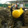
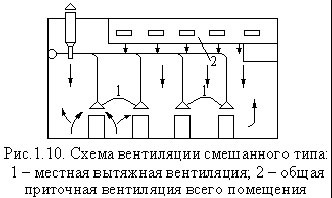
The possible concentration of indoor air contaminated with dust, water vapor and gases, products of thermal processing of food, forces the installation of ventilation systems. In order for these systems to be effective, serious calculations have to be made, including the calculation of the area of \u200b\u200bair ducts.
Having clarified a number of characteristics of the facility under construction, including the area and volume of individual rooms, the features of their operation and the number of people who will be there, specialists, using a special formula, can establish the design ventilation performance. After this, it becomes possible to calculate the cross-sectional area of \u200b\u200bthe duct, which will provide the optimal level of ventilation of the interior.
Why do I need to know about the area of \u200b\u200bair ducts?
Ventilation is a rather complicated system. One of the most important parts of the air distribution network is a complex of ducts. From a qualitative calculation of its configuration and working area (both the pipe and the total material necessary for the manufacture of the duct), not only the correct location in the room or cost savings depends, but most importantly - the optimal ventilation parameters that guarantee a person comfortable living conditions.

Figure 1. The formula for determining the diameter of the working line.
In particular, it is necessary to calculate the area in such a way that the result is a structure capable of transmitting the required amount of air, subject to other requirements for modern ventilation systems. It should be understood that the correct calculation of the area leads to the elimination of air pressure losses, compliance with sanitary standards in terms of speed and noise level of air flowing through the ducts.
At the same time, an accurate idea of \u200b\u200bthe area occupied by the pipes makes it possible to designate the most suitable place in the room under the ventilation system.
Back to the table of contents
How to calculate the area of \u200b\u200bthe used material?
The calculation of the optimal duct area is directly dependent on such factors as the volume of air supplied to one or several rooms, its speed and loss of air pressure.
At the same time, the calculation of the amount of material necessary for its manufacture depends both on the cross-sectional area (dimensions of the ventilation channel), and on the number of rooms into which fresh air must be pumped, and on the design features of the ventilation system.
When calculating the cross-sectional value, it should be borne in mind that the larger it is, the lower will be the speed of air passage through the duct pipes.
At the same time, there will be less aerodynamic noise in such a highway, for the operation of forced ventilation systems less energy will be required. To calculate the area of \u200b\u200bair ducts, it is necessary to apply a special formula.
To calculate the total area of \u200b\u200bthe material that you need to take to assemble the ducts, you need to know the configuration and basic dimensions of the designed system. In particular, for calculating round air distribution pipes, such quantities as the diameter and total length of the entire line will be required. At the same time, the volume of material used for rectangular structures is calculated based on the width, height and total length of the duct.
In general calculations of material requirements for the entire line, it is also necessary to take into account taps and half-taps of various configurations. So, correct calculations of a round element are impossible without knowledge of its diameter and angle of rotation. In calculating the area of \u200b\u200bthe material for the rectangular outlet, such components as the width, height and angle of rotation of the outlet are involved.
It is worth noting that for each such calculation, its own formula is used. Most often, pipes and fittings are made of galvanized steel in accordance with the technical requirements of SNiP 41-01-2003 (Appendix H).
Back to the table of contents
Air duct area calculation
The size of the ventilation pipe is affected by such characteristics as the mass of air pumped into the premises, the speed of the flow and the level of its pressure on the walls and other elements of the main.
It is enough, not having calculated all the consequences, to reduce the diameter of the line, as soon as the speed of the air flow increases, which will lead to an increase in pressure along the entire length of the system and in the places of resistance. In addition to the appearance of excessive noise and unpleasant vibration of the pipe, electrical will also record an increase in energy consumption.
However, it is far from always in the pursuit of eliminating these shortcomings that the cross section of the ventilation duct can and should be increased. First of all, the limited dimensions of the premises may prevent this. Therefore, you should especially carefully approach the process of calculating the area of \u200b\u200bthe pipe.
To determine this parameter, you must apply the following special formula:
Sc \u003d L x 2.778 / V, where
Sc is the calculated channel area (cm 2);
L is the flow rate of air moving through the pipe (m 3 / hour);
V is the air velocity along the ventilation line (m / s);
2,778 is the coefficient of coordination of varieties (for example, meters and centimeters).

The calculation result - the estimated pipe area - is expressed in square centimeters, since in these units of measurement it is considered by specialists as the most convenient for analysis.
In addition to the estimated cross-sectional area of \u200b\u200bthe pipeline, it is important to establish the actual cross-sectional area of \u200b\u200bthe pipe. It should be borne in mind that for each of the main section profiles - round and rectangular - its own separate calculation scheme is adopted. So, to fix the actual area of \u200b\u200bthe circular pipeline, the following special formula is used.
Maintaining a good indoor climate is a very important problem in the operation of any building. Removing contaminated, supplying clean and fresh air becomes the first task in maintaining the required microclimate parameters. An additional function in this case is the storage of heat in the premises.
This function has now begun to occupy a particularly important place in the design and operation of buildings, since many already built facilities do not satisfy modern regulatory documents and acts with this parameter. The most suitable solution to both problems is the use of modern ventilation systems.
There are a fairly large number of options for the execution of these systems, each of which has its pros and cons. But still there is one thing in them that unites them. It is this “something” that the ventilation pipes are.
Types of pipes for ventilation
Pipes are usually classified according to the following parameters:
In shape:
- round section (spiral-wound, straight-seam);
- rectangular section;
- non-standard section (combined, cropped, truncated)
According to the material:
- from aluminum;
- galvanized steel;
- from stainless steel;
- from plastic (polyvinyl chloride, polyurethane, polypropylene);
- from polyester fabric.

Plastic pipes for ventilation
Pipes made of plastic in general have a number of undoubted advantages:
- resistance to moist and aggressive environments;
- not susceptible to corrosion;
- complete tightness;
- aesthetics;
- light weight;
- low cost;
- non-toxicity;
- unification of products.
Subspecies plastic pipes for ventilation, in turn, have the following advantages:
- Polyvinyl chloride:
- resistant to ultraviolet radiation;
- ease of installation.
- Polyurethane:
- significant degree of flexibility;
- durability;
- resistant to chemical attack.
- Polypropylene:
- high strength;
- resistance to aggressive environments;
- service life more than 25 years.
In their properties, pipes made of plastic are much superior to pipes made of alternative materials. So, for example, they have a significant drawback in the form of accumulation of excess static voltage in the ventilation system. Plastic has no such drawbacks.
But nothing is perfect. Plastic, like any other material, has its own "weaknesses". These include vulnerability to high temperatures and open flames.
Galvanized pipes for ventilation
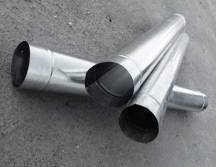
Galvanized pipes for ventilation
The use of galvanized pipes is most rational in the following conditions:
- temperature of transported air is not higher than 80 degrees Celsius;
- humidity is less than 60%.
Ignoring these conditions leads to damage to the protective layer, peeling of zinc.
The most significant advantages of the products are:
- low weight of the structure;
- low cost;
- ease of installation;
- simple operation.
The disadvantages are the limited use and accumulation of static electricity during operation.
Corrugated pipes

Corrugated Pipes for Ventilation
This type of ventilation pipe is usually made of aluminum or steel, which allows the use of such pipes under very high temperatures (up to 900 degrees Celsius). In addition, corrugated pipes are not inclined to accumulate static electricity and are quite aesthetic.
In general, eliminating the shortcomings of galvanized and plastic pipes for ventilation, corrugated nevertheless could not avoid one significant drawback: their inner surface, which is not smooth enough, creates additional aerodynamic drag.
Dimensions and diameters of pipes for ventilation
The smallest cross-sectional area of \u200b\u200bventilation pipes is taken, as a rule, at least 15 by 15 centimeters or 150 millimeters in diameter. The next condition for the selection of pipe size is resistance to wind exposure. Outwardly vented pipes must withstand gusts of wind up to 25-30 meters per second, otherwise it is necessary to increase the cross-section of the pipe to prevent possible damage.
Also, the size of the pipes is selected based on the requirements:
For residential premises, the air flow should be:
- or at least three cubic meters per square meter of area;
- or 20 cubic meters per hour for temporary visitors and 60 cubic meters per hour for permanent residents.
For utility structures - from 180 cubic meters per hour.
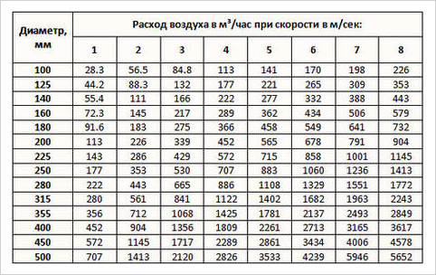
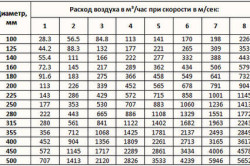
Table for selecting the diameter of pipes for air ducts
Calculation of pipes for ventilation is carried out:
- according to the formula;
- according to the table;
- using programs.
To calculate according to the formula, it is necessary to take into account the volume of the room, the required volume of air.
According to the table, the height of the pipes is determined, which depends on two parameters: the width and diameter of the pipes.
The calculation of the program is simpler. This is expressed at least in the fact that the program allows you to take into account the average temperature outside and inside, the shape of the duct, resistance to air movement, roughness of the inner surface.
Duct Mounting Options
Before installing ventilation systems, you should carefully study the space-planning solution of the premises, as well as the thermotechnical parameters of the fence structures. Then, the operating conditions are evaluated: the presence of harmful substances and aggressive environments, high temperatures or an open flame.
The installation itself is carried out taking into account the above factors, as well as the requirements for the noise level in the premises. So, if the ventilation pipes have many turns or transitions to different diameters, then the ventilation system will be too “noisy”, therefore it is recommended to reduce their number.
On the other hand, space-planning decisions of premises may not allow to reduce the number of turns, etc. That is why it is important to know what noise level is permissible in each particular case. A careful selection of splitters, carried out taking into account the source material of the pipes, can also help in solving the problem.
Pipes for ventilation are usually fastened with:
- clamps;
- hairpins;
- R-, Z- and V-shaped brackets;
- punched tape;
- anchors;
- clamps.

In order for the air exchange in the house to be “correct”, even at the stage of drawing up the ventilation project, aerodynamic design of the air ducts is needed.
Air masses moving along the channels of the ventilation system, when calculating, are accepted as incompressible fluid. And this is quite acceptable, because too much pressure is not formed in the ducts. In fact, pressure is generated as a result of air friction against the walls of the channels, and even when local resistances appear (these include pressure - pressure - jumps at the places of changing directions, when connecting / disconnecting air flows, in areas where control devices are installed or where the diameter of the ventilation duct changes).
Note! The concept of aerodynamic calculation includes determining the cross-section of each of the sections of the ventilation network that provide the movement of air flows. Moreover, the injection resulting from these movements is also determined.

In accordance with many years of experience, we can safely say that sometimes some of these indicators during the calculation are already known. The following are situations that are often encountered in such cases.
- The cross-sectional index of the transverse channels in the ventilation system is already known, it is necessary to determine the pressure that may be required in order for the right amount of gas to move. This often happens in those air conditioning pipelines where section sizes were based on technical or architectural specifications.
- We already know the pressure, but we need to determine the cross section of the network to provide the ventilated room with the required amount of oxygen. This situation is inherent in natural ventilation networks, in which the already existing pressure cannot be changed.
- It is not known about any of the indicators, therefore, we need to determine both the pressure in the highway and the cross section. This situation is found in most cases in the construction of houses.
Features of aerodynamic calculations
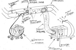
We will get acquainted with the general methodology for carrying out such calculations, provided that both the cross section and the pressure are unknown to us. Immediately make a reservation that the aerodynamic calculation should be carried out only after the required volumes of air masses are determined (they will pass through the air conditioning system) and the approximate location of each of the air ducts in the network is designed.

And in order to carry out the calculation, it is necessary to draw an axonometric diagram in which there will be a list of all network elements, as well as their exact dimensions. In accordance with the plan of the ventilation system, the total length of the air ducts is calculated. After that, the entire system should be divided into segments with uniform characteristics, according to which (only individually!) The air flow will be determined. What is characteristic, for each of the homogeneous sections of the system, a separate aerodynamic calculation of the air ducts should be carried out, because each of them has its own speed of movement of air flows, as well as a permanent flow rate. All obtained indicators must be included in the axonometric diagram already mentioned above, and then, as you probably already guessed, it is necessary to choose the main highway.
How to determine the speed in the ventilation ducts?
As can be judged from everything said above, it is necessary to choose the chain of consecutive segments of the network that is the longest as the main highway; however, the numbering should begin exclusively from the most remote area. As for the parameters of each of the sections (and these include air consumption, the length of the section, its serial number, etc.), they should also be entered in the calculation table. Then, when the application is finished, the cross-sectional shape is selected and its - sections - dimensions are determined.

LP / VT \u003d FP.
What do these abbreviations mean? Let's try to figure it out. So, in our formula:
- LP is the specific air flow in the selected area;
- VT is the speed at which the air masses in this area move (measured in meters per second);
- FP - this is the desired cross-sectional area of \u200b\u200bthe channel.
What is characteristic, when determining the speed of movement, it is necessary to be guided, first of all, by considerations of economy and noise of the entire ventilation network.
Note! According to the indicator obtained in this way (we are talking about the cross section), it is necessary to select a duct with standard values, and its actual cross section (indicated by the abbreviation FF) should be as close as possible to the previously calculated one.
LP / FF \u003d VF.
Having received an indicator of the required speed, it is necessary to calculate how much the pressure in the system will decrease due to friction against the walls of the channels (for this it is necessary to use a special table). As for the local resistance for each of the sections, they should be calculated separately, and then summarized in the total indicator. Then, by summing up the local resistance and losses due to friction, you can get a general indicator of losses in the air conditioning system. In the future, this value will be used in order to calculate the required amount of gas masses in the ventilation channels.

Air heating unit
Earlier we talked about what an air-heating unit is, talked about its advantages and areas of application, in addition to this article, we advise you to familiarize yourself with this information
How to calculate the pressure in the ventilation network
In order to determine the estimated pressure for each individual section, you must use the formula below:
H x g (pH - PB) \u003d DPE.
Now let's try to figure out what each of these abbreviations means. So:
- H in this case denotes the difference in the marks of the shaft mouth and the intake grille;
- PB and LV is an indicator of gas density, both outside and inside the ventilation network, respectively (measured in kilograms per cubic meter);
- finally, DPE is an indicator of what natural available pressure should be.
We continue to disassemble the aerodynamic design of the ducts. To determine the internal and external density, it is necessary to use the reference table, while the temperature indicator inside / outside must be taken into account. As a rule, the standard temperature outside is taken as plus 5 degrees, and regardless of in which specific region of the country construction work is planned. And if the outside temperature is lower, then as a result the injection into the ventilation system will increase, due to which, in turn, the volumes of incoming air masses will be exceeded. And if the temperature outside, on the contrary, is higher, then the pressure in the line will decrease because of this, although this nuisance, by the way, can be compensated by opening the window panes / windows.
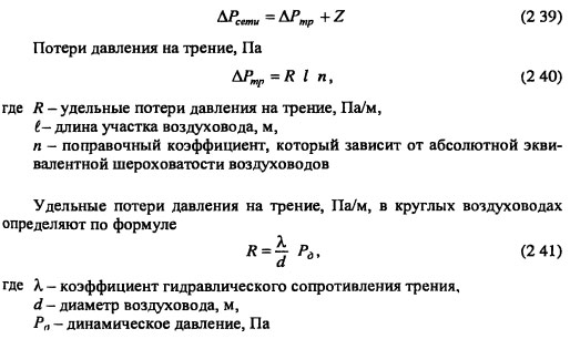
As for the main task of any described calculation, it consists in choosing such ducts where the losses on the segments (we are talking about the value? (R * l *? + Z)) will be lower than the current DPE or, alternatively, at least equal his. For greater clarity, we give the above moment in the form of a small formula:
DPE? ? (R * l *? + Z).
Now we will examine in more detail what the abbreviations used in this formula mean. Let's start from the end:
- Z in this case is an indicator indicating a decrease in air velocity due to local resistance;
- ? - this value, more precisely, the coefficient of what is the roughness of the walls in the highway;
- l is another simple value that denotes the length of the selected section (measured in meters);
- finally, R is an indicator of friction losses (measured in pascals per meter).


![]()
Well, we figured it out, now we’ll find out a little more about the roughness index (that is?). This indicator depends only on what materials were used in the manufacture of channels. It is worth noting that the speed of air movement can also be different, so this indicator should be taken into account.
Speed \u200b\u200b- 0.4 meters per second
In this case, the roughness indicator will be as follows:
- for plaster using a reinforcing mesh - 1.48;
- in slag gypsum - about 1.08;
- conventional brick - 1.25;
- and slag concrete, respectively, 1.11.
Speed \u200b\u200b- 0.8 meters per second
Here the described indicators will look as follows:
- for plastering using reinforcing mesh - 1.69;
- for slag gypsum - 1.13;
- for ordinary brick - 1.40;
- finally, for slag concrete - 1.19.
Slightly increase the speed of the air masses.
Speed \u200b\u200b- 1.20 meters per second
For this value, the roughness indices will be as follows:
- for plaster using a reinforcing mesh - 1.84;
- in slag gypsum - 1.18;
- ordinary brick - 1.50;
- and, therefore, for slag concrete - somewhere around 1.31.
And the last indicator of speed.
Speed \u200b\u200b- 1.60 meters per second
Here the situation will look like this:
- for plaster using a reinforcing mesh, the roughness will be 1.95;
- for slag gypsum - 1.22;
- for ordinary brick - 1.58;
- and finally, for slag concrete - 1.31.
Note! We figured out the roughness, but it is worth noting one more important point: it is advisable to take into account the insignificant margin, which varies between ten and fifteen percent.
We deal with the general ventilation calculation
When performing aerodynamic calculation of air ducts, you must take into account all the characteristics of the ventilation shaft (these characteristics are listed below in a list).
- Dynamic pressure (to determine it, use the formula - DPE? / 2 \u003d P).
- Air mass flow (it is indicated by the letter L and is measured in cubic meters per hour).
- Pressure loss due to air friction against the inner walls (indicated by the letter R, measured in pascals per meter).
- The diameter of the ducts (to calculate this indicator, the following formula is used: 2 * a * b / (a \u200b\u200b+ b); in this formula, the values \u200b\u200bof a, b are the dimensions of the cross sections of the channels and are measured in millimeters).
- Finally, speed is V, measured in meters per second, as we mentioned earlier.
 >
>
As for the immediate sequence of actions in the calculation, it should look something like this.
Step one. First, you need to determine the required channel area, for which the following formula is used:
I / (3600xVpek) \u003d F.
We deal with the values:
- F in this case is, of course, the area that is measured in square meters;
- Vpek is the desired air velocity, which is measured in meters per second (for channels, the speed is 0.5-1.0 meters per second, for mines - about 1.5 meters).
Step Three The next step is to determine the appropriate diameter of the duct (indicated by the letter d).
Step Four Then the remaining indicators are determined: pressure (denoted as P), speed (abbreviated V) and, therefore, decrease (abbreviated R). For this, it is necessary to use nomograms according to d and L, as well as the corresponding coefficient tables.
Fifth step. Using already other coefficient tables (we are talking about indicators of local resistance), it is necessary to determine how much air exposure will decrease due to local resistance Z.
Step Six At the last stage of the calculations, it is necessary to determine the total losses on each individual segment of the ventilation line.
Pay attention to one important point! So, if the total loss is lower than the already existing pressure, then such a ventilation system can be considered effective. But if the losses exceed the pressure indicator, then it may be necessary to install a special throttle diaphragm in the ventilation system. Thanks to this diaphragm the excess pressure will be extinguished.
Also note that if the ventilation system is designed to service several rooms at once, for which the air pressure must be different, then during the calculations it is also necessary to take into account the discharge or back-up rate, which must be added to the overall loss indicator.
Video - How to make calculations using the VIKS-STUDIO program
Aerodynamic design of air ducts is considered a mandatory procedure, an important component of planning ventilation systems. Thanks to this calculation, you can find out how effectively the rooms are ventilated with a particular section of the channels. And the effective functioning of ventilation, in turn, provides maximum comfort for your stay in the house.
An example of calculations. The conditions in this case are as follows: an administrative building, has three floors.

Although there are many programs for, many parameters are still determined in the old fashion, using formulas. The calculation of the ventilation load, area, power and parameters of the individual elements is carried out after drawing up the scheme and distribution of equipment.
This is a difficult task that only professionals can do. But if you need to calculate the area of \u200b\u200bsome ventilation elements or the cross-section of the ducts for a small cottage, you can actually manage it yourself.
Air exchange calculation

If the room does not have toxic emissions or their volume is within acceptable limits, air exchange or ventilation load is calculated by the formula:
R= n * R1,
here R1 - the need for air of one employee, in cubic meters \\ hour, n - the number of permanent employees in the room.
If the volume of the room per employee is more than 40 cubic meters and works natural ventilation, no need to calculate air exchange.
For premises for domestic, sanitary and utility purposes, the calculation of ventilation by hazard is carried out on the basis of the approved norms of the frequency of air exchange:
- for office buildings (extractor hood) - 1.5;
- halls (supply) - 2;
- conference rooms for up to 100 people with a capacity (for supply and exhaust) - 3;
- lounges: influx 5, extractor hood 4.
For industrial premises where hazardous substances are constantly or periodically released into the air, ventilation is calculated according to hazard.
Hazardous air exchange (vapors and gases) is determined by the formula:
Q= K\(k2- k1),
here TO - the amount of steam or gas that appears in the building, in mg \\ h, k2 - the content of steam or gas in the outflow, usually the value is equal to the MPC, k1 - gas or steam content in the supply.
The concentration of harmful substances in the inflow is allowed up to 1/3 of the maximum permissible concentration.
For rooms with excess heat, air exchange is calculated by the formula:
Q= Ghutsc(tyx — tn),
here Gizb - excess heat pulled out is measured in watts, from - specific heat capacity by mass, s \u003d 1 kJ, tyx - temperature of the air removed from the room, tn - inflow temperature.
Heat load calculation

Calculation of the thermal load on ventilation is carried out according to the formula:
Qin \u003dVn *k * p * Cr(tbn -tnro)
in the formula for calculating the thermal load on ventilation Vн - the external volume of the structure in cubic meters, k - air exchange rate, tvn - the temperature in the building is average, in degrees Celsius, tnro - the air temperature outside used in the calculation of heating, in degrees Celsius, r - air density, in kg \\ cubic meter, Wed - heat capacity of air, in kJ \\ cubic meter Celsius.
If the air temperature is lower tnro the rate of exchange of air decreases, and the rate of heat consumption is considered equal Qvconstant value.
If, when calculating the heat load of ventilation, it is impossible to reduce the rate of air exchange, the heat consumption is calculated by the heating temperature.
Heat consumption for ventilation
The specific annual heat consumption for ventilation is calculated as follows:
Q \u003d * b * (1-E),
in the formula for calculating the heat consumption for ventilation Qo - total heat loss of the building during the heating season, Qb - household heat input, Qs - heat input from outside (sun), n - coefficient of thermal inertia of walls and floors, E - reduction factor. For individual heating systems 0,15 for central 0,1 , b - heat loss coefficient:
- 1,11 - for tower structures;
- 1,13 - for multi-section and multi-entrance buildings;
- 1,07 - for buildings with warm attics and basements.
Calculation of the diameter of the ducts

Diameters and cross-sections are calculated after the general scheme of the system is compiled. When calculating the diameters of ventilation ducts, the following indicators are taken into account:
- Air volume (supply or exhaust), which must pass through the pipe for a given period of time, cubic meter \\ h;
- Air speed If the flow velocity is underestimated in the calculation of ventilation pipes, air ducts of too large a section will be installed, which entails additional costs. Excessive speed leads to the appearance of vibrations, an increase in the aerodynamic drone and an increase in the power of equipment. The speed of movement on the tributary is 1.5-8 m / s, it varies depending on the site;
- The material of the ventilation pipe. When calculating the diameter, this indicator affects the resistance of the walls. For example, the highest resistance is black steel with rough walls. Therefore, the estimated diameter of the ventilation duct will have to be slightly increased compared to the standards for plastic or stainless steel.
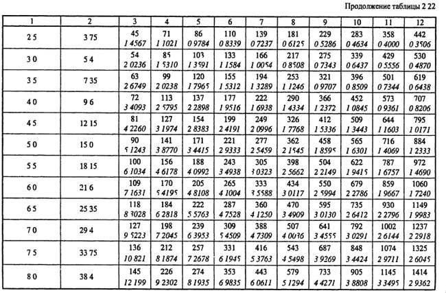
Table 1. Optimum airflow rate in ventilation pipes.
When the capacity of future ducts is known, the cross section of the ventilation duct can be calculated:
S= R\3600 v,
here v - air velocity, in m \\ s, R - air consumption, cubic meters \\ h.
The number 3600 is a time coefficient.
![]()
here: D - diameter of the ventilation pipe, m
Calculation of the area of \u200b\u200bventilation elements
The calculation of the ventilation area is necessary when the elements are made of sheet metal and it is necessary to determine the quantity and cost of the material.
The area of \u200b\u200bventilation is calculated by electronic calculators or special programs, many of which can be found on the Internet.
We will give several tabular values \u200b\u200bof the most popular ventilation elements.
| Diameter mm | Length m | |||
| 1 | 1,5 | 2 | 2,5 | |
| 100 | 0,3 | 0,5 | 0,6 | 0,8 |
| 125 | 0,4 | 0,6 | 0,8 | 1 |
| 160 | 0,5 | 0,8 | 1 | 1,3 |
| 200 | 0,6 | 0,9 | 1,3 | 1,6 |
| 250 | 0,8 | 1,2 | 1,6 | 2 |
| 280 | 0,9 | 1,3 | 1,8 | 2,2 |
| 315 | 1 | 1,5 | 2 | 2,5 |
table 2. The area of \u200b\u200bdirect round ducts.
The value of the area in sq. M. at the intersection of horizontal and vertical stitches.
| Diameter mm | Angle | ||||
| 15 | 30 | 45 | 60 | 90 | |
| 100 | 0,04 | 0,05 | 0,06 | 0,06 | 0,08 |
| 125 | 0,05 | 0,06 | 0,08 | 0,09 | 0,12 |
| 160 | 0,07 | 0,09 | 0,11 | 0,13 | 0,18 |
| 200 | 0,1 | 0,13 | 0,16 | 0,19 | 0,26 |
| 250 | 0,13 | 0,18 | 0,23 | 0,28 | 0,39 |
| 280 | 0,15 | 0,22 | 0,28 | 0,35 | 0,47 |
| 315 | 0,18 | 0,26 | 0,34 | 0,42 | 0,59 |
Table 3. Calculation of the area of \u200b\u200bbranches and semi-branches of circular cross-section.
Calculation of diffusers and gratings
Diffusers are used to supply or remove air from the room. The purity and air temperature in each corner of the room depend on the correct calculation of the number and location of ventilation diffusers. If you install more diffusers, the pressure in the system will increase, and the speed will drop.
The number of ventilation diffusers is calculated as follows:
N= R\(2820 * v * D * D),
here R - throughput, in cubic meters \\ hour, v - air speed, m \\ s, D - diameter of one diffuser in meters.
The number of ventilation grilles can be calculated by the formula:
N= R\(3600 * v * S),
here R - air flow in cubic meters \\ hour, v - air velocity in the system, m \\ s, S - sectional area of \u200b\u200bone lattice, sq.m.
Channel heater calculation

The calculation of an electric type ventilation heater is as follows:
P= v * 0,36 * ∆ T
here v - the volume of air passed through the heater in cubic meters / hour, ∆T - the difference between the temperature of the air outside and inside, which must be provided to the heater.
This indicator varies between 10 - 20, the exact figure is set by the client.
The calculation of the heater for ventilation begins with the calculation of the frontal cross-sectional area:
Af \u003dR * p\3600 * Vp,
here R - the volume of the intake flow, cubic meter \\ h, p - the density of atmospheric air, kg \\ cubic meter, Vp - mass air velocity at the site.
The cross-sectional size is necessary to determine the dimensions of the ventilation heater. If, according to the calculation, the cross-sectional area is too large, it is necessary to consider the option from the cascade of heat exchangers with the total design area.
The mass velocity index is determined through the frontal area of \u200b\u200bthe heat exchangers:
Vp= R * p\3600 * Af.fact
For further calculation of the ventilation heater, we determine the amount of heat needed to warm the air flow:
Q=0,278 * W * c (Tp-Ty)
here W - consumption of warm air, kg \\ hour, Tp - supply air temperature, degrees Celsius, To - street temperature, degrees Celsius, c - specific heat of air, a constant value of 1.005.